Optimization of automotive oil pump body die-casting process

Summary

In order to meet requirements of high air tightness and high strength of automotive aluminum alloy oil pump body die-casting parts, to solve problems of shrinkage and cavity defects in castings, die-casting process was designed and optimized. First, casting process was analyzed, pouring overflow system was designed based on experience and process parameters were initially selected. Then Taguchi orthogonal test method was used to design a 5-factor, 4-level die-casting process parameter scheme, and Procast was used for numerical simulation. 16 sets of orthogonal test results were subjected to range and variance analysis based on signal-to-noise ratio. Results showed that mold temperature has the most significant impact on shrinkage and shrinkage cavities. Optimal process parameters of five factors are: pouring temperature 650 ℃, mold temperature 240 ℃, slow/fast injection distance 200 mm/60 mm, fast injection speed 3.0 m/s, slow injection speed 0.2 m/s. Numerical simulation results show that shrinkage and shrinkage volume of casting under this process parameter combination is 1.067 cm³, which is 26.5% lower than before optimization. Mold test results show that appearance of casting is intact, and X-ray flaw detection in key parts shows no obvious shrinkage cavities; metallographic microscope (OM) and scanning electron microscope (SEM) are used to observe structure of casting, and it is found that structure of each area of casting is dense; mechanical property test shows that, microhardness of die casting is greater than HV85, average tensile strength of test rod under same process is 253.36 MPa, and casting meets usage requirements.
Automobile oil pump body is a pressure-bearing sealing part. It works in high temperature, high pressure and engine oil environments, has high requirements for high temperature corrosion resistance and air tightness. Due to sensitivity of new energy vehicles to cruising range, their demand for lightweighting is more significant than that of traditional fuel vehicles. Aluminum alloys have become preferred material for automotive parts such as oil pump bodies for oil trucks and hybrid vehicles due to its high specific strength and corrosion resistance. High-pressure casting has advantages of high production efficiency, high dimensional accuracy of castings, good surface and mechanical properties. Therefore, it is widely used in production of complex parts such as aluminum alloy cylinder blocks, pump bodies, and shells. However, due to improper processes and other reasons, die-cast seals often have pores, shrinkage cavities, and shrinkage defects. Existence of pore defects will reduce strength and air tightness of sealing castings, making them unusable.
Reasonable die-casting process parameters are a necessary condition for obtaining qualified castings, but there are many factors that affect quality of castings, and value ranges of each factor are wide. Obtaining reasonable process parameters often requires a large number of tests. Use of numerical simulation combined with orthogonal experiments can effectively determine reasonable process parameters. Li Yang et al. used a combination of orthogonal experiments and numerical simulations to explore effects of mold temperature, fast and slow pressure switching points and fast injection speed on pores of aluminum alloy motorcycle cylinders. Results showed that pore area of casting is negatively correlated with fast injection speed, positively correlated with speed switching point and mold temperature. ApparaoK C et al. explored effects of pouring temperature, injection pressure, pouring time and mold temperature on pores of aluminum alloy castings. They concluded that pouring temperature and mold temperature have a significant impact on pores of castings, and an orthogonal experiment based on signal-to-noise ratio was used to optimize process parameters with the smallest pores. GuptaAK et al. used genetic algorithm and fuzzy logic method to obtain optimal combination of five die-casting process parameters including solidification time, pouring temperature, injection pressure and die-casting machine plunger speed, which reduced probability of die-casting defects such as shrinkage holes and cracks in aluminum alloy carburetor shell castings by 58.28%.
In summary, it is common and efficient to use numerical simulation combined with optimization methods such as orthogonal experiments or genetic algorithms to optimize die-casting process, and effect of reducing porosity of die-casting parts is also very significant. However, above studies have not completely selected influencing factors of casting porosity defects, research on influencing factors of individual shrinkage porosity and shrinkage cavity defects also needs to be in-depth. Therefore, in order to explore influence of various factors in die-casting process on shrinkage and cavity defects in oil pump body, this article selects main die-casting process parameters of pouring temperature, mold temperature, slow/fast injection distance, fast injection speed and slow injection speed. Using a combination of orthogonal experiments and numerical simulations based on signal-to-noise ratio, shrinkage and porosity rates of castings are optimized as indicators in order to find the best combination of process parameters for castings under a specific pouring and overflow system design.

1. Die-casting process analysis and pouring overflow system design

1.1 Analysis of die-casting process of oil pump body parts

Oil pump body is a pressure-resistant seal that has high requirements for strength and air tightness. Therefore,defects such as cracks, looseness, and bubbles are not allowed in sealing area of casting. Defects such as strain, undercasting, mold sticking, and cold shutoff are not allowed on the surface. Surface roughness is not greater than Ra=6.3 μm, and dimensional tolerance should meet requirements of GB/T 6414-2017.
Outline dimensions of oil pump body are 203.9 mm * 108.5 mm * 154.8 mm. Weight of casting blank is 0.65 kg, volume is about 240 cm³, maximum projected area is 109.6 c㎡, and maximum cross-section is surface I, which is assembly surface of pump body and pump cover. Considering that castings II and III require lateral core pulling, casting can choose I side as main parting surface and use bottom injection pouring. Oil pump body model and wall thickness are shown in Figure 1.

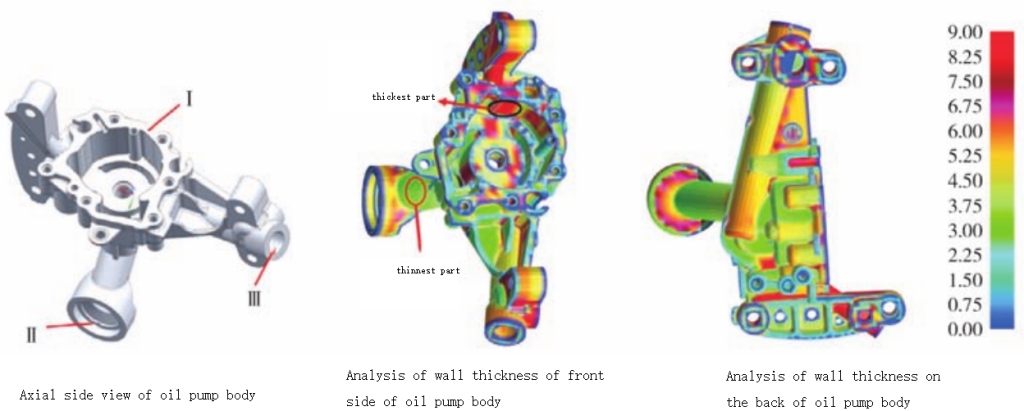
Figure 1 Three-dimensional model of oil pump body and analysis of its wall thickness
Oil pump body casting has an irregular structure and uneven wall thickness. Maximum wall thickness in sealing area reaches 13.6 mm, the thinnest wall thickness is only 1.5 mm, and average wall thickness is about 4.5 mm. According to casting structure and die-casting empirical formula, process parameters of casting can be preliminarily determined as follows: pouring temperature 660 ℃, mold temperature 210 ℃, slow/fast injection distance 195 mm/65 mm, fast injection speed 2.75 m/s, slow injection speed is 0.25 m/s.
Since ADC12 alloy has advantages of good casting performance, high strength, low density and low shrinkage, this alloy is selected as material for oil pump body casting. Its alloy composition is shown in Table 1.

SiCuMnMgFeZnPb, Ti, Sn, CdNiAl
10.351.950.250.240.720.61Each contains 0.10.04margin

Table 1 Chemical composition of ADC12 alloy wB/%

1.2 Design of pouring and overflow system

Oil pump body is a cylinder-type casting with a complex structure, uneven wall thickness, and is concave in multiple directions. It requires side core pulling, so die-casting mold can only use one mold and one cavity. Based on projected area of casting, structure of casting and its ideal injection pressure range, a 500 t horizontal cold press chamber die-casting machine was selected. The total length of press chamber is 515 mm and punch diameter is 75 mm. In order to ensure smooth flow of molten metal during mold filling process, prevent air entrainment, and facilitate removal of pouring system, a “comb-shaped” side pouring method with 6 trapezoidal lateral runner was designed. The total area of inner runner is 221 mm2, gate is set at upper edge of oil pump body and protruding parts on both sides, as shown in Figure 2.

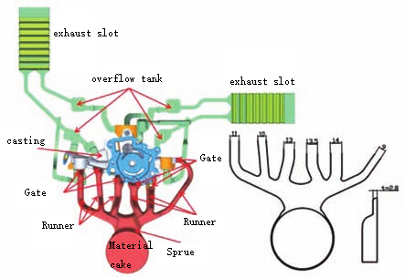
Figure 2 Design of pouring and draining system for oil pump body casting
Pouring and overflow system of oil pump body casting consists of a cake, a sprue, 6 lateral sprues, 6 injectors, 8 overflow slots and 2 exhaust slots. Main parameters of each part are shown in Table 2 Show.

Total volume V/cm3Casting volume V/cm3Gating system volume Vg/cm3Overflow system volume Ve/cm3Gate cross-sectional area Ag/mm2Casting surface area Af/cm2Casting solidification modulus M/cm
61324028390221942.55

Table 2 Main parameters of pouring and drainage system

2. Orthogonal design of die-casting parameters and optimization of process parameters

2.1 Initial and boundary conditions of numerical simulation of die casting

On the premise of ensuring reliable numerical simulation results and reducing calculation time as much as possible, this study uses Procast software to divide non-uniform grids. Set grid unit size in thinner wall thickness of molten metal filling areas such as castings, gating systems and overflow systems to 1.5 mm, and set grid unit size in other areas to 3 mm, set grid unit size of metal parts such as molds, barrels and punches to 10 mm. The total number of grids is approximately 4.54 million. Casting material is ADC12 aluminum alloy, mold material is H13 hot work die steel, and initial conditions of materials are same as those in literature.

2.2 Die-casting numerical simulation plan and results

Oil pump body castings have high requirements for internal quality and air tightness, defects such as cracks, looseness, and bubbles are not allowed inside castings. There are many factors that affect die-casting quality. Relevant production practices and literature research show that process parameters that have an important impact on forming quality of cylinder die-casting parts are pouring temperature (A), mold operating temperature (B), and slow/fast injection distance (C), fast injection speed (D) and slow injection speed (E). Therefore, these five parameters are selected as influencing factors of shrinkage and cavity defects in orthogonal test of this article. Other parameters are set to a certain value according to actual production situation, and their influence is not considered for the time being. 5-factor 4-level orthogonal test parameters are formulated as shown in Table 3.

LevelFactor
Pouring temperature/℃Mold temperature/℃Slow/fast injection distance/mmfast injection speed/(m*s-1)slow injection speed/(m*s-1)
1630180180/802.00.1
2650200190/702.50.2
3670220200/603.00.3
4690240210/503.50.4

Table 3 Factors and levels of orthogonal test
This article conducts tests in accordance with L16 (45) standard orthogonal test plan, uses Procast’s Visual-Cast module to conduct numerical simulations of die-casting filling and solidification process, prediction of shrinkage and porosity defects. Using shrinkage porosity and shrinkage porosity as evaluation indicators, use cutoff-info function in Procast Visual-Viewer module to count the total shrinkage porosity index of casting, which is volume of part above 3% (hereinafter referred to as shrinkage porosity volume, V-shrinkage). The larger volume, the greater probability that shrinkage holes will appear in corresponding parts of casting. Results of numerical simulation cross test of 5-factor and 4-level die-casting parameters are shown in Table 4.

2.3 Die-casting parameter simulation orthogonal test optimization results and analysis

2.3.1 Analysis of orthogonal test results based on signal-to-noise ratio

Signal-to-noise ratio is used as basis for judging stability of test. Large-scale characteristics, small-scale characteristics and large-scale characteristics will be selected according to different applications. Purpose of orthogonal test in this study is to reduce shrinkage cavity volume of casting, so small characteristics were chosen. If small characteristic does not take a negative value, the smaller value, the better. Signal-to-noise ratio criterion is shown in Equation (1).

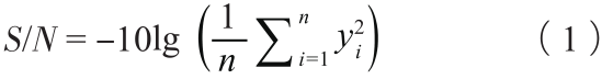
In formula: S/N is signal-to-noise ratio; yi is i-th test result, and n is number of tests.
Lower part of Table 4 is range table of signal-to-noise ratio corresponding to shrinkage pore volume of oil pump body casting. Ki is average value of signal-to-noise ratio of all shrinkage pore volumes under i-th level of different factors. Figure 3 is a line chart of level of each factor in casting and average signal-to-noise ratio of shrinkage pore volume. It can more intuitively reflect influence of each factor on shrinkage pore volume of casting than range chart line chart.

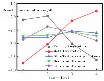
Figure 3 Influence of levels of various die casting factors on shrinkage and shrinkage cavities
The greater signal-to-noise ratio, the smaller volume of predicted shrinkage porosity index. As can be seen from Figure 3, the best process parameter values after optimization of orthogonal test are: pouring temperature 650 ℃, mold temperature 240 ℃, slow/fast injection distance 200/60 mm, fast pressing speed 3.0 m/s, slow pressing speed 0.2 m/s.
Table 5 shows variance analysis of each process factor. F critical value is 2.490. When F>F critical value, it means that this factor has a significant impact on shrinkage and cavity defects of castings. Based on analysis of Table 4 and Table 5, it can be concluded that influence of various factors on shrinkage and shrinkage holes of castings is: mold temperature > pouring temperature > slow injection speed > slow/fast injection distance > fast injection speed. That is to say, influence of mold temperature is significant, influence of pouring temperature is relatively significant, influence of slow/fast injection distance and slow injection speed is not significant, and influence of fast injection speed is minimal.

Test numberTest planNumerical simulation results
ABCDEShrinkage volume/cm2Signal to noise ratio/dB
1630180180/806301801.497-3.50
2630200190/706302001.301-2.29
3630220200/606302201.153-1.24
4630240210/506302401.178-1.42
5650180190/706501801.452-3.24
6650200180/806502001.315-2.38
7650220210/506502201.319-1.13
8650240200/606502401.141-1.15
9670180200/606701801.526-3.67
10670200210/506702001.473-3.36
11670220180/806702201.384-2.82
12670240190/706702401.282-2.16
13690180210/506901801.683-4.52
14690200200/606902001.601-4.09
15690220190/706902201.483-3.42
16690240180/806902401.322-2.42
Signal-to-noise ratioMean K1-2.112-3.732-2.780-2.720-2.857Range analysis 
Mean K2-1.795-3.030-2.777-2.695-2.377Influence levelB>A>E>C>D
Mean K3-3.002-2.152-2.537-2.695-2.575  
Mean K4-3.612-1.788-2.607-2.537-2.893  
Extremely bad R1.6371.9440.2430.1580.516  
OptimizationA2B4C3D3E2  

Table 4 L16(45) orthogonal simulation test results

FactorSum of squared deviationsDegrees of freedomF valueF critical valueSignificance
A7.17032.0662.490Relatively significant
B9.22032.6572.490Significantly
C0.18030.0522.490Not obvious
D0.06730.0192.490Minimal impact
E0.71630.2062.490Not obvious
Error17.3515   

Table 5 Variance analysis results

2.3.2 Die casting filling and solidification analysis

Above-mentioned optimal die-casting process parameters and parameters before optimization were selected and simulated in Procast respectively. The total filling time before and after optimization was 0.802 s and 1.002 s respectively. Filling process is shown in Figure 4. It can be seen from Figure 4 that during filling process before optimization, when the first stream of molten metal passes through inner runner (slow pressure distance 195 mm), it begins to enter rapid injection stage. Flow speed of molten metal suddenly increases, it is sprayed from inner runner at a very high speed, hits core and cavity wall, violently scouring mold, which not only causes splashing, but also shortens life of mold. When filling is 69.7%, molten metal passing through two sprues on the right side of casting merges at maximum wall thickness of casting at a very high speed. The two molten metals collide with each other, forming a turbulent flow and involving a large amount of gas, which oxidizes molten metal and reduces feeding ability, increasing tendency of shrinkage and shrinkage cavities. In addition, wall thickness here of casting is the largest, heat dissipation during cooling process is slow and it is easy to form an isolated liquid phase area, which makes exhaust difficult, further increasing possibility of forming pores.
Slow injection speed of optimized post-filling process is small. During slow pressing, injection punch moves at a smaller speed. Molten metal flows calmly in pressure chamber and slowly fills mold cavity in a laminar flow manner, without involving a large amount of air. At the same time, a smaller slow pressing speed and a longer slow pressing distance correspond to a longer slow pressing time. Gas in cavity during filling process has more time to be eliminated, which reduces probability of pores in casting. Optimized slow injection stroke is 200 mm. When molten metal fills about 15% of cavity volume (including castings, overflow and exhaust systems) through inner runner at a slow injection speed, it enters rapid injection stage. Front part of molten metal that enters mold cavity is filled slowly, and quickly filled part of metal at the back has front part of molten metal as a buffer to reduce direct impact on mold, thereby extending life of mold. When filling 69.8%, speed of the two molten metals that merge at maximum wall thickness of casting is small and will not violently disturb each other to form severe turbulence, reducing tendency of casting to form pores.

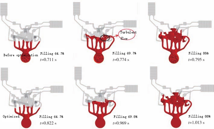
Figure 4 Comparison of casting filling process before and after process optimization

2.3.3 Die-casting solidification process and defect analysis

Time when the overall solidification fraction of two sets of process plans before and after optimization is 96% is 31.4s and 34.6s respectively. Time difference is not big. Solidification process of castings before and after optimization is also similar, as shown in Figure 5. Solidification starts at thin wall of casting, exhaust groove and the two outer sprues, then solidifies at thick wall of casting, overflow tank and three middle sprues, finally solidification of final filling area of casting and material cake. From perspective of the overall solidification sequence, maximum wall thickness of casting is after runner and overflow tank solidify, forming an isolated liquid phase area. This area does not receive external feeding during solidification process, shrinkage pit defects are easily formed. In actual production process, it is necessary to increase cooling rate and prioritize solidification to reduce degree of shrinkage defects or avoid their occurrence.

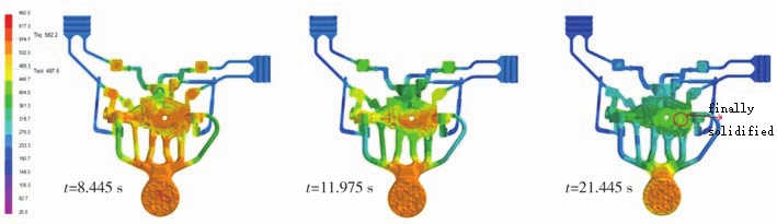
Figure 5 Casting solidification process
Critical feeding solid phase ratio of ACD12 aluminum alloy is 0.7. It is generally believed that after solidification fraction of casting is greater than 70%, molten metal no longer has macroscopic feeding ability. When solidification fraction of casting is 70%, a comparative analysis of final solidified area of casting before and after optimization process is performed, as shown in Figure 6.

Figure 6 Comparison of isolated liquid phase area at maximum wall thickness of casting before and after process optimization
Solid phase rate in this area of casting before and after optimization is lower than 100%, and temperature is higher than surrounding temperature of casting, which further proves that an isolated liquid phase region appears here in casting. However, cross-sectional area of isolated liquid phase area after optimization is significantly smaller than before optimization, indicating that optimization of process parameters can significantly improve shrinkage defects of castings.
As can be seen from Figure 7, the overall shrinkage and cavity defects of casting are significantly reduced after optimization. Before optimization, single largest shrinkage cavity index volume appears at maximum wall thickness A of casting with a volume of 0.988 cm³, and probability is 48.14%, which is likely to form shrinkage defects. After optimization, index volume at A is 0.762 cm³, probability is 24.65%, and probability of shrinkage defects is reduced. After optimization, volume and probability of shrinkage defects in the overall casting and at maximum wall thickness are reduced compared with before optimization. The overall shrinkage porosity index volume of casting before and after optimization is 1.452 cm³ and 1.067 cm³ respectively. After optimization, shrinkage porosity index volume is reduced by 26.5% compared with before optimization.

Figure 7 Comparison of shrinkage and cavity defects in oil pump body castings before and after process optimization
Reason for reduction of shrinkage porosity defects in oil pump body castings is firstly because pouring temperature of optimized molten metal is 10℃ lower, and cooling volume of the molten metal shrinks less, resulting in a smaller volume of shrinkage cavities; secondly, after optimization, the mold temperature is 30℃ higher, temperature difference between mold and molten metal is small, flow and feeding ability of molten metal is stronger, and tendency to form shrinkage holes is smaller; thirdly, after optimization, slow injection distance is long and speed is slow, so that molten metal flows slowly, does not involve too much gas to oxidize and reduce feeding ability; fourth, after optimization, injection speed is fast, injection specific pressure is large, volume of casting shrinks during solidification process. When runner still has ability to feed, higher pressure will push more molten metal in gating system to feed, reducing shrinkage and cavity defects in castings.

3. Casting quality analysis

Using die-casting mold in Figure 8a and optimized process parameters for trial production, formed oil pump body casting is shown in Figure 8b. It can be seen from Figure 8b that front and back surfaces of casting are smooth and clean, without defects such as cracks, strains, bulges, and undercasting. Surface quality meets process requirements.

Figure 8 Die casting production
In order to check internal quality of casting, X-ray flaw detection was performed on it, and results are shown in Figure 9. Comparing flaw detection results in Figure 9 with numerical simulation prediction results in Figure 7, it can be seen that location of shrinkage holes in oil pump body casting is basically consistent with prediction results, which shows that prediction results of simulation test are relatively accurate. Locations of tiny shrinkage cavities in casting are A and B in Figure 9. These two locations are outer areas of casting and have little impact on sealing performance of oil pump body. In production, taking appropriate spot cooling measures to increase cooling rate here can reduce probability of holes.

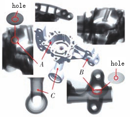
Figure 9 X-ray flaw detection results
In order to further analyze internal structure and quality of oil pump body casting, thin-walled part and maximum wall thickness A of casting in Figure 9 were cut and sampled for observation with a metallographic microscope (OM). It can be seen from Figure 10a that solidification process at position C of thin wall of casting has fast heat dissipation, large undercooling, high nucleation rate, and short solidification time. Relatively small spherical primary α-Al phase and fine strip-like Al-Si eutectic phase are obtained. Grain size is relatively fine and distribution is relatively uniform. Thin wall C of oil pump body solidifies preferentially under high pressure, so structure is dense and has no shrinkage defects. Scanning electron microscopy (SEM) and OM observation were performed on thick wall A of casting, as shown in Figure 10b. Grains at thick wall A of oil pump body are relatively coarse and uneven in size. Metallographic structure is mainly a coarse massive primary α-Al phase and a needle-like Al-Si eutectic phase. Fine Si particles are embedded in primary α-Al phase for strengthening, and fine shrinkage defects are distributed at the junction of two phases. Grain size is larger at thick wall of casting, and there are shrinkage defects, as shown in Figure 10b. Coarse needle-shaped Al-Si eutectic has a stronger splitting effect on matrix than strip-shaped one, so structural mechanical properties of thick-walled part of casting must be worse than those of thin-walled part.
A sample was taken from thick wall A for tensile testing, and its cross section was observed by SEM. As shown in Figure 10c, tensile section is uneven, with a large number of cleavage planes and tearing edges. Cleavage surface is large and there are a few dimples. It is a fracture mode that mixes brittle fracture and ductile fracture. It is a quasi-cleavage fracture, which is consistent with low toughness of ADC12 material.
In order to verify whether mechanical properties of casting meet usage requirements, 5 points are taken for hardness testing at thick wall A of casting. As shown in Figure 10d, minimum microhardness in sampling point is HV85.4, average microhardness at thick wall A is HV93.4, and hardness of ADC12 aluminum alloy oil pump body is required to be no less than HV85. At the same time, 5 B-type tensile specimens were die-cast with same molten aluminum furnace and same process parameters for tensile testing. Average tensile strength of sample is 236.6 MPa, which meets domestic requirement of tensile strength ≥ 230 MPa for corresponding brand YZAlSi11Cu3 alloy. Therefore, oil pump body casting meets mechanical property requirements of product.

Figure 10 OM, SEM structure, tensile fracture morphology, tensile strength and microhardness of oil pump body casting

4 Conclusion

(1) Taguchi orthogonal simulation test results show that influence of various die-casting process factors on shrinkage and shrinkage holes in oil pump body castings is: mold temperature > pouring temperature > slow injection speed > slow/fast injection distance > fast injection Speed, among which mold temperature has a significant impact, pouring temperature has a significant impact, slow/fast injection distance and slow injection speed have no significant impact, and fast injection speed has the least impact.
(2) Optimized process parameters are: pouring temperature 650 ℃, mold temperature 200 ℃, slow/fast injection distance 200/60 mm, fast injection speed 3.0 m/s, slow injection speed 0.2 m/s . Numerical simulation results show that using this set of process parameters, molten metal filling during die-casting process is stable, and shrinkage porosity volume index is the smallest, which is 26.5% lower than before optimization. Predicted location of shrinkage cavities is basically consistent with the X-ray flaw detection results.
(3) Castings tested using optimized process parameters have a good appearance, sealing area has a dense structure, there are no obvious shrinkage holes and cracks. Maximum wall thickness of casting is a quasi-cleavage fracture, which is consistent with low toughness of ADC12 material. Average tensile strength of tensile specimens under same aluminum melt furnace and same process parameters is 236.6 MPa, average microhardness of thick wall of casting is HV93.4, and oil pump body casting meets usage requirements.

Improve performance of die-casting molds and extend service life of die-casting molds

Pressure casting (die casting for short) has characteristics of high production efficiency, short production process, high casting finish and strength, small machining allowance, and saving of metal materials. China’s die-casting industry has developed rapidly in recent years, with total output increasing significantly, and it has become a veritable die-casting power. Molds, die-casting machines and die-casting materials are the three major elements of die-casting production. Only high-quality molds can produce high-quality castings stably and efficiently. Working environment of die-casting molds is very harsh: During die-casting production process, mold cavity is in direct contact with high-temperature, high-pressure, and high-speed molten metal, and is directly washed by molten metal. It is prone to wear, high-temperature oxidation, and various corrosions: high-efficiency production causes mold temperature to rise and fall dramatically periodically, and working surface is prone to thermal fatigue cracks: when metal is forced to deform, it rubs against surface of cavity, easily wearing out mold and reducing its hardness. Mold cost is high, production cycle is long, and repair is difficult. Service life is also particularly important. Therefore, research on factors that affect mold performance and service life is beneficial to improving casting quality and reducing economic losses caused by early scrapping of molds. Generally speaking, factors that affect performance and service life of die-casting molds include mold materials, mold design and manufacturing, surface treatment technology and specific usage of mold.

Die-casting molds are very expensive special precision machinery, which require mold maintenance workers not only to have superb skills and meticulous work style, but also to be serious and responsible. Mold maintenance workers should be familiar with technical standards of die-casting molds as follows:
1. It is all about cleaning metal cracks and scales everywhere in mold to reveal true color of mold.
2. Refer to the last die-cast product sent for repair together with mold to carefully check problems with mold. Is there any strain, sticking to mold, pressure or loss of flesh? Is there any small core that is bent or broken? Is there any movable core that is inserted incorrectly in position? Is there a broken push rod or a change in length of push rod? Is there any insert that is not positioned correctly? Is there fastening bolts are loose, etc. Depending on damage, repair or replacement is determined.
3. For cavity collapse, cracks, falling pieces, etc. that cause slight strain on casting, partial welding repairs can be performed. Welding repairs should be performed strictly according to welding repair process, otherwise a lot of mold life will be lost. Above failures of smaller molded parts are more serious or mold is damaged.
4. If molding surface of larger molded parts is seriously collapsed, cracked, or dropped, it can be repaired locally by welding. Welding repair should be performed strictly according to welding repair process, otherwise a lot of mold life will be lost. Above failures of smaller molded parts are more serious or mold is damaged.
5. Sliding parts such as core pulling mechanisms, guide devices, etc. should be thoroughly cleaned, carefully inspected, and repaired. Re-lubricate with high-temperature grease before assembly.
6. If there is hydraulic core pulling, hydraulic part and mold should be repaired at the same time. When repairing hydraulic part, pay special attention to cleanliness to prevent contamination, otherwise the entire hydraulic system of die-casting machine will be polluted.
7. When mold fails or is damaged during production process, repair plan should be determined according to specific situation. Perform comprehensive repairs as above if necessary.
8. After maintenance of mold has been completed, rust-proof molding surface, parting surface, and installation surface, close and set mold, and place it on backing plate according to installation direction of mold on machine. Mold accessories are placed with mold.

01 Mold material

Performance and service life of die-casting mold are closely related to material of mold. Good die-casting mold manufacturing materials generally have following characteristics: good machinability and forgeability; high wear resistance and corrosion resistance: high strength at high temperatures, high red hardness, high temperature oxidation resistance, impact toughness and tempering stability at high temperatures: good thermal conductivity and fatigue resistance; small thermal expansion coefficient: small heat treatment deformation rate and good hardenability.
In the past, 3Cr2W8V hot work die steel was commonly used in China, and life of die-casting mold was about 50,000 mold times. H13 hot work die steel was introduced in the 1990s, and die-casting molds produced have a service life of 150,000 to 200,000 molds. It is currently a widely used die-casting mold material. 3Cr2W8V hot work die steel has high strength and hardness, good cold and heat fatigue resistance, and good hardenability, but has poor toughness and plasticity, short service life, high alloying degree, and high cost. H13 has good comprehensive properties at medium temperature (~600℃), high hardenability (can be hardened in air), low heat treatment deformation rate, and its performance and service life are higher than 3Cr2W8V.
Material selection of die-casting mold should not only be based on temperature of casting metal and type of casting metal, but also impact and wear of various parts of die-casting mold by casting metal. The higher temperature, the higher thermal fatigue performance and high temperature performance material should have. Parts that are more severely worn should have higher hardness. Working conditions of die-casting molds are becoming increasingly demanding, and requirements for metallurgical quality, performance, and lifespan of mold materials are constantly increasing. In particular, requirements for material purity and isotropy are higher. Some high-alloy, high-quality, and optimized mold materials are constantly emerging. In turn, it also promotes development of die-casting industry.

02 Mold design and manufacturing

Reasonable mold design is an important prerequisite for extending service life of die-casting molds. Reasonable wall thickness and cooling water channel design can ensure strength and thermal balance of mold. When designing mold, special attention should be paid to the areas where stress concentration and greater abrasion occur during work. Accuracy of each selected part must be reasonable: if gap is too large, heat conduction will be poor, leading to thermal fatigue damage; if gap is too small, extrusion force and tensile stress will occur. Internal stress is easily generated during mold manufacturing process, and internal stress has a great impact on service life of mold. Therefore, in process of manufacturing and processing molds, internal stress should be avoided and eliminated in time. For example, after rough machining, timely stress relief and tempering can be performed, and electric pulses can be used instead of electric sparks to reduce surface tension of mold.

03 Mold surface treatment technology

Through rigorous and reasonable technical treatment of surface of die-casting mold, its performance and life can be greatly improved. Die-casting mold surface treatment technology can be roughly divided into three categories: traditional heat treatment process improvement technology; surface modification technology, such as surface laser treatment technology: coating technology.
(1) Improvement technology of traditional heat treatment process. Traditional die-casting mold heat treatment process is quenching-tempering. So-called improvement technology of traditional heat treatment process is to combine quenching-tempering with advanced surface treatment technology. Such as NQN (i.e. carbonitriding-quenching-carbonitriding composite strengthening), surface hardness of mold is higher, internal strength is increased, hardness gradient of casing layer is reasonable, tempering stability and corrosion resistance are improved, the overall performance and service life are greatly improved.
(2) Surface modification technology. Surface modification technology refers to use of physical or chemical methods to change properties of mold surface. Generally speaking, there are two types: surface heat, expansion and penetration technology and surface laser treatment technology. Surface heat, expansion and carburizing technologies include carburizing, nitriding, boronizing, carbonitriding, sulfur carbonitriding, etc. Carburizing helps strengthen surface hardness of mold. Carburizing process methods include solid powder carburizing, gas carburizing, vacuum carburizing, and ion carburizing. Vacuum carburizing and ion carburizing have fast carburizing speed, uniform carburizing layer, gentle carbon concentration gradient and small deformation of workpiece. Nitriding process is simple, and nitrided layer of mold has high hardness, good wear resistance, and good mold sticking resistance. Boriding improves surface properties most obviously, and mold hardness, wear resistance, corrosion resistance and adhesion resistance are significantly improved, but process conditions are harsh.
Laser treatment of mold surfaces is a technology that has emerged in the past thirty years. It improves surface performance of molds in two ways. One is to melt mold surface with laser and then combine it with carburizing, nitriding, plating and other processes. Another method is to combine laser treatment surface technology with some metal auxiliary materials with better physical properties to integrate them into surface of die-casting mold.
(3) Coating technology. Coating technology is to put a layer of protective clothing on mold by coating the surface, such as polytetrafluoroethylene composite plating. Main purpose is to enhance wear resistance, corrosion resistance and cold and heat resistance of mold.

04 Mold use

Choosing a reasonable die-casting process and maintenance are crucial to service life of mold. Most mold damage is caused by improper use and lack of scientific maintenance. First of all, special attention should be paid to temperature control of mold. Mold should be preheated before production and an appropriate temperature range should be maintained during production to prevent surface cracks or even cracking caused by excessive temperature gradients between inner and outer layers of cavity. Secondly, choose a high-quality die-casting release agent with a moderate thickness and evenly coat mold surface, which plays an important role in protecting mold material. Finally, in order to reduce accumulation of thermal stress and avoid cracking of die-casting mold, it is necessary to regularly use techniques such as tempering to eliminate thermal stress.

05 Mold material conclusion

Die-casting mold materials, mold design and manufacturing, mold surface treatment technology and mold usage comprehensively affect performance and service life of mold. Combining these factors and taking effective measures can effectively improve performance of die-casting molds and extend service life of die-casting molds.

Automotive light bracket die-casting process analysis and mold design

Summary

Structural characteristics of automobile light bracket were analyzed, die-casting process was designed, ProCAST software was used to conduct numerical simulation analysis on filling process, die-casting mold heat balance and temperature field of aluminum alloy die-casting, predict location and causes of defects, and optimize mold structure based on prediction results. Actual production shows that use of optimized mold design improves quality of castings.
Car light bracket parts are an important part of car lights. They need to have sufficient strength to support car light housing, need to have high stability and corrosion resistance to ensure that they can be firmly, accurately and stably fixed on car body to ensure safety of driving at night. Aluminum alloy has been widely used in car light brackets due to its good properties. However, due to uneven wall thickness and complex structure of lamp bracket, defects such as shrinkage and cold insulation are prone to occur during die-casting production process, which cannot meet safe driving requirements of car. In order to improve the overall yield rate of a company’s aluminum alloy car light brackets, this study focuses on die-casting forming process of car light bracket parts, conducts CAE analysis of casting filling and solidification process based on ProCAST, improves die-casting process and mold design for possible defects to improve product quality.

1. Car light bracket parts

Structure of car light bracket casting is shown in Figure 1. Material is EN AC44300 aluminum alloy, and its chemical composition is shown in Table 1. Structure of car light bracket parts is relatively complex, and it is generally plate-shaped. There are some lines on plate to ensure optical performance, and there are also many rib structures. Main wall thickness of casting is 3 mm, but local wall thickness varies greatly. Minimum wall thickness of ribs is 1.2 mm, and maximum wall thickness is 8.4 mm. The overall dimensions are 190.3 mm * 191.88 mm * 74.22 mm, and weight is 613.5 g. Surface of casting is required to be free of burrs and scratches, and there are no casting defects such as shrinkage cavities, shrinkage porosity, cracks, and cold shuts inside, so as to meet strength requirements of bracket parts.

Automotive light bracket die-casting

Figure 1 Casting structure of car light bracket

SiFeCuMnZnMgNiSnAl
10.5≤1.0≤0.10≤0.55≤0.15000margin

Table 1 Chemical composition of EN AC44300 aluminum alloy wB/%

2. Die-casting process and mold design

2.1 Parting surface selection

According to structural characteristics of lamp bracket casting, parting surface is selected on plane where top mounting hole has the largest projected area of casting.

2.2 Sprue design

Gating system not only plays an important role in controlling flow direction and state of molten metal in mold cavity, exhaust conditions, and pressure transmission of mold, but can also adjust filling speed, filling time, and temperature distribution of mold.
In order to make process of molten metal as short as possible, reduce unnecessary heat loss, and to avoid molten metal from directly impacting core, ingate position is set at the top of casting and straight edges at both ends, as shown in Figure 2. Calculation of cross-sectional area of gate:

Automotive light bracket die-casting

In formula: A is cross-sectional area of gate, c㎡; G is weight of molten metal passing through gate, g; ρ is density of molten metal, g/cm³; v is filling speed of molten metal flowing through inner runner, m/s; t is filling time, s. Filling speed is 30 m/s, filling time is 0.04 s, and wall thickness of gate is 1.5 mm. Calculated cross-sectional area of gate is 253 mm2.
Structural form and size of runner mainly depend on shape and size of die casting and shape, position, direction and size of ingate. Recommended calculation formula for thickness of runner is:
                                    D=(5~8)T(2)
In formula: D is thickness of lateral runner, mm; T is thickness of inner runner, mm. Thickness of lateral runner is taken to be 8 mm. In order to facilitate demoulding of casting, demoulding slope of lateral runner is set to 15°.
A horizontal cold chamber die-casting machine was selected, punch diameter was selected as 70 mm, and material handle thickness was set to 18 mm.

2.3 Overflow tank design

During process of filling mold cavity with molten metal, try to eliminate gas in cavity and cold metal liquid at the front end. By setting up an overflow tank, thermal balance of mold can be improved and quality of die castings can be improved. Area around hole in casting is where molten metal converges, it is easy to generate eddy currents and entrap gas. Therefore, overflow groove is set outside hole and at final filling place. At the same time, for processing, overflow groove will be mainly set on movable mold. Gating system for this part is shown in Figure 2.

Automotive light bracket die-casting

Figure 2 Watering and drainage system design

2.4 Cooling system

Cooling system has a decisive influence on forming quality of die-cast products. Figure 3 shows layout of cooling water channels inside die-casting mold for this product. Water channels are evenly distributed around casting, which is conducive to a uniform mold temperature field.

Automotive light bracket die-casting

Figure 3 Distribution of cooling water channels

2.5 Mold structure

Length and width of core of this mold are 350 mm and 300 mm respectively. Mold core structure is shown in Figure 4. Fixed mold core contains insert 1, and movable mold core part contains insert 2. Surrounding shape of casting is formed by three slide blocks. In order to facilitate maintenance and replacement, reduce costs, replaceable long pin cores are made in 17 deep holes.

Automotive light bracket die-casting

Figure 4 Mold core structure

3. CAE analysis

3.1 Preprocessing

HyperMesh software is used to perform CAE pre-processing on casting to obtain a high-quality surface mesh model, which is then input into MeshCAST module of ProCAST software to create a volume mesh. Set grid unit size respectively: 1 mm for casting, 2 mm for movable mold core, fixed mold core, slider, core and water channel, the overall mesh number is 19.54 million, mesh model of casting and mold is shown in Figure 5.

Automotive light bracket die-casting

Figure 5 Mesh division of castings and molds

3.2 Numerical simulation analysis

3.2.1 Initial and boundary conditions

Mold material is H13 steel, and die-casting process parameters are shown in Table 2. Heat transfer coefficient between mold and casting is set to 20 000 W/(㎡·K), heat transfer coefficient between movable mold and fixed mold is 1 000 W/(㎡·K), heat transfer coefficient between mold and air is 100 W/(㎡·K), heat transfer coefficient between release agent and mold is set to 100 W/(㎡·K). Heat transfer coefficient between cooling water and mold is 5 000 W/(㎡·K), temperatures of cooling water and release agent are both 20℃.

Casting temperature/℃Mold preheating temperature/℃Gate speed/(m*s-1)Holding time/s
68022038

Table 2 Die casting process parameters
Die-casting production cycle is divided into four stages, and corresponding times are shown in Table 3. Forming cycle is 50 s.

Liquid metal filling, pressure holding and solidificationOpen mold and take out castingSpray release agentClose mold
20s15s5s10s

Table 3 Die casting forming cycle

3.2.2 Analysis of filling process

Figure 6 shows filling process of molten metal. The entire filling time is 0.042 s. At the beginning, molten metal first fills thin plate part of casting heat sink after passing through ingate, then enters mold cavity from both ends through inner sprues on both sides. After middle filling is completed, molten metal flows to the top until it is full, and finally fills overflow tank farthest from sprue. However, during filling process of molten metal, there are still problems with setting of runner. Part of molten metal will first fill thin plate part of heat sink through middle runner, then enter mold cavity through outer runner. There are multiple strands multiple strands of molten metal flowing together, which can easily form cold insulation and air entrapment, as shown circled in Figure 6d. Gating system is basically reasonable, but there is still room for optimization and improvement.

Automotive light bracket die-casting

Figure 6 Filling process of lamp bracket casting

3.2.3 Mold thermal balance and temperature field analysis

In order to meet requirements of product quality and production efficiency, thermal balance analysis is used to obtain temperature distribution and change trend in mold cavity during die-casting process, which helps to determine sensitive areas of temperature control, take measures to reduce temperature fluctuations, achieve uniformity control of mold temperature field, and provide a reference for formulating reasonable temperature field planning. A uniform mold temperature field will not only extend service life of mold, but also improve quality of castings. Therefore, it is very important to conduct thermal balance analysis and temperature field analysis of mold.
Select a point on the surface of casting, fixed mold and movable mold, as shown in Figure 7, and draw temperature-time curve, as shown in Figure 8. It can be seen that after 12 die-casting cycles, mold has basically reached a thermal equilibrium state.

Automotive light bracket die-casting

Figure 7 Selected points on casting, fixed mold and movable mold

Automotive light bracket die-casting

Figure 8 Three-point temperature-time curve
After mold reaches thermal equilibrium, temperature field of next cycle is selected for analysis. As shown in Figure 9, from left to right are temperature distributions of movable mold, fixed mold and fixed mold insert in three stages before filling, pressure-holding solidification and release agent spraying. Before filling, temperature field distribution of mold is relatively uniform. When molten metal is filled, surface temperature of mold cavity will rise sharply as molten metal enters. During pressure-holding and solidification stage, heat exchange between mold and cooling water and heat dissipation into air cause temperature to gradually drop. Because cavity structure is complex, temperature field is not uniform, and local temperature is high, resulting in a certain difference in solidification time of each part of casting, but the overall temperature field has a small temperature gradient on cavity surface; When mold is opened and parts are taken out, mold surface is in large contact with air. At the same time, under action of release agent, surface temperature of mold cavity decreases rapidly, surface temperature of most of mold cavity and insert drops to below 500℃.
Judging from analysis results of mold temperature field, temperature field distribution on the surface of movable mold and fixed mold cavity is relatively uniform, but local temperature is too high and there are hot spots, so there is still room for optimization.

Automotive light bracket die-casting process analysis

Figure 9 Temperature fields of movable mold, fixed mold and fixed mold insert at different times in one cycle

3.2.4 Defect analysis

Figure 10 shows distribution of shrinkage cavities and shrinkage porosity in bracket die-casting. It can be seen that shrinkage cavities and porosity in casting are concentrated at rib structural connections of heat dissipation lamellae on bracket parts, and at locations with larger wall thickness around holes. Occurrence of these positional defects is mainly because temperature during solidification in these areas is relatively high, solidification time of molten metal is longer, and solidification rate is uneven. When it is completely solidified, molten metal cannot be fed, shrinkage cavities and shrinkage porosity defects appear. In addition, due to complex structure of this casting, improper adjustment of cooling system and uneven heat dissipation, heat accumulation may occur, causing internal temperature of casting to be too high, resulting in cold insulation defects, which will have a certain impact on product quality. Therefore, this solution still needs to be further improved so that produced bracket parts can meet required performance requirements.

Automotive light bracket die-casting process analysis

Figure 10 Distribution of shrinkage cavities and porosity in castings

4. Process improvement and die-casting production

In order to improve phenomenon that flow of sprues at both ends of casting is insufficient and flow is small under influence of core on one side, resulting in confluence of multiple strands of molten metal to form cold isolation and air entrapment, a total of three in-runners are added at confluence at both ends and at location where molten metal is insufficiently filled on one side, as shown in red circle in Figure 11, to make filling process smoother and more uniform; and since overflow groove cannot be installed on heat dissipation sheet, in order to improve exhaust condition of ribs, an ejector rod is added, which eliminates cold separation and improves forming quality of casting.

Automotive light bracket die-casting process analysis

Figure 11 Distribution of shrinkage cavities and porosity in castings after process optimization
After process optimization, numerical simulation predicts distribution of shrinkage cavities and shrinkage porosity in castings, as shown in Figure 11. X-ray non-destructive testing was performed on casting, and results are shown in Figure 12. Through comparison, it was found that flaw detection results were basically consistent with numerical simulation results. Die-casting parts had shrinkage holes in the thickest parts, and there were no pores exceeding Ф0.3 mm in flat corrugations and ribs, which met quality requirements.

Automotive light bracket die-casting process analysis

Figure 12 X-ray non-destructive testing results
After improving pouring system of mold, practical applications show that continuous production efficiency of mold is high, 600 pieces/8 h, yield rate reaches 96%, and mold life reaches 150,000 molds. Die casting with pouring system is shown in Figure 13 shown.

Automotive light bracket die-casting process analysis

Figure 13 Actual die casting

5 Conclusion

Designed die-casting process and mold for aluminum alloy lamp bracket casting, conducted CAE analysis on casting filling process, temperature field, shrinkage cavity and porosity defects. Based on analysis results, die-casting mold design was optimized, gating system and exhaust system were improved, optimized mold design was used to produce a lamp bracket casting product that met quality requirements.

Die casting production case! Research on vacuum die-casting LED lamp radiator castings

Magnesium alloy has characteristics of high specific strength and specific stiffness, good impact resistance, excellent electromagnetic shielding and thermal conductivity, and easy recycling. It also has good casting performance and corrosion resistance, is widely used in aviation, aerospace, 3C and other industries. For example, magnesium alloy can replace aluminum alloy and be used to prepare high-power LED radiators. To obtain magnesium alloy die-casting parts with dense structure and good performance, vacuum die-casting is one of main forming methods. In view of shortcomings of current vacuum die-casting such as low cavity pumping efficiency, unreliable vacuum valve closing, slow vacuum valve response, and high price, a vacuum pumping system containing full-process and half-process exhaust channels was designed. When performing vacuum die casting, reasonable process parameters can obtain good quality die castings. Preliminary research found that fast injection speed has a great impact on structural properties and mechanical properties of vacuum die castings. Therefore, it is of positive significance to study influence of different fast injection speeds on quality of magnesium alloy vacuum die castings. Taking AZ91D magnesium alloy as research object, three sets of vacuum die-casting tests were conducted using a self-designed vacuum pumping system to study effects of different fast injection speeds on mechanical properties and structure of vacuum die-casting parts.

Graphical results

A large AZ91D magnesium alloy LED lamp radiator is used as the target product, and Solidworks software is used to conduct a three-dimensional solid modeling of radiator. Its structural diagram is shown in Figure 1. Size of casting is 220mm*130mm*170mm, and thickness is uneven. The thickest is 8mm, the thinnest is 1.8mm, and average thickness is 4.5mm. Heat sink is the thinnest, a cylindrical push rod position is set at an appropriate position on each heat sink to ensure that the entire die casting is evenly stressed during demoulding process and facilitates smooth demoulding. Gating system is designed according to structural characteristics and forming method of casting.
Test was conducted on a DM400 horizontal cold chamber die-casting machine. In order to protect mold, improve forming efficiency of castings, and reduce scrap rate, an AODE oil circulating mold temperature machine was used to preheat mold to 200℃. Schematic diagram of vacuum exhaust system is shown in Figure 2. Working principle of vacuum pumping system containing full-process and half-process exhaust channels is as follows: before start of die-casting, main valve is closed, and vacuum pump begins to continuously pump air from vacuum tank to achieve a preset vacuum level. When die casting starts, half-process exhaust solenoid valve is open. When molten metal enters pressure chamber through pouring port, injection punch starts to inject. When injection punch crosses pouring port and touches induction switch, main valve opens, vacuum tank simultaneously evacuates mold cavity through full-process exhaust channel and half-process exhaust channel. When injection punch pushes metal liquid forward and triggers fast injection induction switch, half-process exhaust solenoid valve is quickly closed by electromagnetic force, while full-process exhaust channel continues to pump air into cavity, as shown in Figure 2b. When metal liquid fills mold cavity, enters curved and narrow exhaust channel to cool and solidify, pumping stops. At this time, a vacuum die-casting test is completed and a vacuum die-casting part is obtained.

die-casting LED lamp

Figure 1 3D model of die casting

Density/(g*cm-3)Thermal conductivity/(W*m-1*K-1)Latent heat of fusion/(kJ*kg-1)Specific heat capacity/(kJ·kg-1.K-1)
1.70284341.61.42

Table 1 Thermophysical parameters of AZ91D magnesium alloy

die-casting LED lamp

Figure 2 Schematic diagram of vacuum pumping system

1. Static mold 2. Moving mold 3. Vacuum tank 4. Vacuum pump 5. Pour port 6. Punch 7. Pressure chamber 8. Cavity 9. Solenoid valve 10. Half-process exhaust channel 11. Full-process exhaust channel 12.Master valve

NoFast injection speed/(m*s-1)Slow injection distance/mmSlow injection distance/mmInjection specific pressure/MPa
L130.212084
L240.212084
L350.212084

Table 2 Die casting process parameters
Vacuum die casting is shown in Figure 3. Observation shows that vacuum die-casting parts of three sets of radiators are complete in appearance, there is no phenomenon of insufficient charging, and there is almost no difference in appearance. Careful observation revealed that part of heat sink in L1 has a cold insulation, as shown in Figure 4. Therefore, when product is subjected to static load or cyclic stress, it is easy to crack or even break, which seriously affects the safety of the product. In addition, surface flow marks also appear. This is due to low injection speed of fast injection mold. Molten metal that first enters die-casting mold cavity forms a thin and incomplete metal layer, which is covered by subsequent molten metal and leaves traces, thus affecting surface quality of die-casting part. See Figure 4b. No obvious cold insulation and surface flow mark defects were found in L2 heat sink; due to high injection speed of L3, when molten metal quickly fills cavity, it has a great impact and is prone to flash, which increases cost and time of product machining, causes material waste, and shortens life of mold.

die-casting LED lamp

Figure 3 Radiator vacuum die casting

die-casting LED lamp

Figure 4 L1 heat sink surface defects
A number of ordinary die-casting parts and vacuum die-casting parts were produced using L1~L3 process parameters. Ordinary die-casting parts and vacuum die-casting parts produced in the three groups of experiments were sampled respectively. Sampling locations were divided into two parts: second part of heat sink and bottom plate, as shown in Figure 2. Metallurgical crystalline samples and tensile samples were taken using wire-cut electric discharge machines, and JHY-5000 electronic universal testing machine was used to test mechanical properties of heat sink. It can be seen that L1 heat sink has larger shrinkage cavities and a wider distribution of shrinkage porosity; L2 heat sink has a smaller shrinkage range and smaller size; L3 heat sink has larger shrinkage cavities and shrinkage porosity. L1 base plate has smaller shrinkage cavities but they are widely distributed; L2 base plate has a small amount of shrinkage porosity and smaller shrinkage holes; L3 base plate has multiple shrinkage porosity and shrinkage holes. Analysis shows that using a self-designed vacuum pumping system can extract most of gas from mold cavity, so internal pores of vacuum die-casting parts are reduced. However, due to different fast injection speeds, vacuuming time is different, final air pressure of mold cavity is also different, and flow state of metal in cavity is also different. Therefore, shrinkage porosity and shrinkage holes of vacuum die-casting parts produced by three groups of experiments are also different.

NoVacuum die castingOrdinary die casting
Tensile strength/MPaElongation/%Tensile strength/MPaElongation/%
L11852.81661.3
L22265.41993.2
L32114.61912.9
Average2074.31852.5

Table 3 Mechanical properties of heat sink

die-casting LED lamp

Figure 5 Microstructure of vacuum die-casting heat sink

die-casting LED lamp

Figure 6 Microstructure diagram of vacuum die-cast radiator bottom plate

In conclusion

(1) A new vacuum pumping system was used to conduct a vacuum die-casting test. Results show that magnesium alloy radiator vacuum die-casting parts have a complete appearance, less cold insulation, and a reduced number of cracked parts. Compared with ordinary die-casting parts with same process parameters, average tensile strength is increased by 12% and elongation is increased by 72%.
(2) When fast injection speed is high, vacuum die castings are prone to casting defects such as shrinkage and shrinkage holes; when fast injection speed is low, casting defects such as cold shuts and surface flow marks are prone to occur, thus affecting final quality of product.
(3) Under conditions of fast injection speed of 4m/s, slow injection speed of 0.2m/s, slow injection distance of 120mm, and injection specific pressure of 84MPa, magnesium alloy vacuum die-casting parts with complete appearance, dense structure and good mechanical properties can be obtained.

Analysis and solutions for thermal cracking of die-cast ADC12 aluminum alloy mobile phone middle frame

Abstract: Causes of thermal cracking of middle frame of die-cast ADC12 aluminum alloy mobile phones were analyzed using methods such as direct reading spectrometer, scanning electron microscope and metallographic inspection. Results show that hot cracking occurs at grain boundary, with a large number of pores and carbon-oxygen inclusions distributed on both sides, and there are more massive β (Al9Fe2Si2) brittle phases, which hinders feeding channel of alloy, increase brittleness of alloy, and worsen mechanical properties of material. At the same time, due to influence of thermodynamic factors during cooling process, internal structure is unevenly distributed, resulting in large thermal stress, which causes thermal cracks in the middle frame of mobile phone during die-casting process.
With development of 5G communications, traditional metal casings have a strong shielding effect on mobile phone signals. Current mainstream appearance material in the development of smartphones uses a double glass/ceramic + aluminum alloy mid-frame solution. Compared with deformed aluminum alloy mobile phone middle frames, die-cast aluminum alloy middle frames have advantages of excellent formability, simple process, and high production efficiency. ADC12 aluminum alloy die-casting parts are very suitable for mass production due to their high yield, good surface quality, high dimensional accuracy and low subsequent processing volume, and are widely used in automotive and electronic communications fields. As a core structural component, middle frame of a mobile phone plays an important supporting role in smartphones and has high requirements in terms of strength. In casting production, hot cracks may have serious consequences, especially mechanical properties will be seriously affected, resulting in product scrapping. Currently, research on ADC12 aluminum alloy mainly focuses on optimization of alloy composition, there are few reports on distribution of structural defects during die-casting process and impact of defects on mechanical properties of alloy. This article uses optical microscope, scanning electron microscope, direct reading spectrometer and other means to observe and analyze thermal cracking defects in the middle frame of mobile phones made of ADC12 aluminum alloy die-casting. It uses direct reading spectrometer and other methods to observe and analyze, and then proposes improvement measures to provide a reference for avoiding such defects in production process of mobile phone middle frames.

1.Test materials and methods

1.1 Alloy composition

Main raw material used for ADC12 aluminum alloy in this test is recycled aluminum. Chemical composition of sample near fracture is analyzed using a direct reading spectrometer and compared with standard composition. Results are shown in Table 1. It can be seen that composition of hot cracked sample is within standard range.
Main chemical composition of ADC12 alloy

ProjectSiMgFeTiCuMnZnAl
Standard9.6-12.0≤0.3≤1.3≤0.31.5-3.5≤0.5≤1.0Margin
Hot cracking specimen10.00.20.70.031.70.20.8Margin

1.2 Pressure casting process

Clamping force of die-casting machine used is 300kN, material handle thickness is 15mm, mold temperature is 200℃, injection force is 330kN, punch diameter is 60mm, injection pressure is 116MPa, injection time is 3.5s, cooling time is 2.0s, and mold retention time is 8.0s. In this test, mold was preheated to 150℃ (actually measured temperature of mold surface) through a mold temperature machine, and then die-casting was performed. Action stroke position of mold handle during die-casting process: the first fast position is 100mm, the second fast position is 240mm, boost position is 280mm, and tracking position is 375mm. Macro photo of middle frame of produced mobile phone and its thermal crack defect is shown in Figure 1. It can be seen from figure that thermal crack occurs at hot joint of casting. This is because at the end of solidification of alloy, temperature of molten metal drops rapidly, which reduces flow rate of molten alloy, easily produces shrinkage porosity and shrinkage holes, and reduces feeding effect of molten metal on cracks.

die-cast ADC12 aluminum alloy mobile phone middle frame

1.3 Organizational performance analysis

Analysis and testing methods such as Phonex scanning electron microscope and metallographic microscope were used to analyze fracture morphology, metallographic structure and micro-region components of cracked specimen.

2. Test results and discussion

2.1 Fracture morphology analysis

Figure 2 shows fracture morphology of thermal crack in the middle frame of mobile phone. From Figure 2a, it can be seen that fracture morphology of thermal crack is relatively rough, its edges are uneven and staggered, there are inclusions on both sides of crack and around it. It can be judged that hot cracking occurs at grain boundary. This is because when alloy solidifies to semi-solid stage, thermal stress at grain boundary gradually increases. At this time, strength limit of alloy is smaller, strength limit of semi-solid state of material is lower than thermal stress at grain boundary. That is, stress and strain generated by shrinkage in final stage of solidification exceed limit range that material can withstand, which is main cause of thermal cracking. Hot cracks generated at this time cannot heal in time, strength of alloy will decrease, and hot cracks will expand further. As can be seen from Figure 2b, there are brittle fracture areas and ductile fracture areas in fracture surface, with brittle fracture being main area. There are a large number of holes concentrated in some areas inside fracture cracks, which are initially determined to be pores. Due to large number of holes, which are widely distributed and relatively dense, they can be judged to be pores caused by recycling of waste materials such as air entrainment and exhaust plates during die casting. They seriously reduce mechanical properties of alloy. Moreover, there are a large number of inclusions distributed around pores. EDS micro-area composition analysis results of each point in Figure 2 are shown in Table 2. It can be seen from Table 2 that each point contains carbon, oxygen, nitrogen, aluminum, silicon and iron elements. It is inferred that it is mainly carbon, oxygen and nitrogen inclusions and harmful iron phase (β-AlFeSi), and it can be speculated that inclusions are derived from auxiliary materials in die-casting process, such as release agents, granular oil, etc., causing specimen to exhibit brittle fracture characteristics.

die-cast ADC12 aluminum alloy mobile phone middle frame

EDS analysis results of each point in Figure 2

LocationAlSiCuFeCON
127.301.94 2.4356.846.125.38
242.32   33.1512.233.74
323.21 6.27 43.3022.21 
416.393.73 6.3269.553.37 

2.2 Structural analysis of alloy

Figure 3 shows microstructure of alloy at hot crack position observed under an optical microscope. Metallographic structure is composed of primary α-Al and α-Al+ eutectic silicon phases. Light color is matrix structure and dark color is eutectic structure. It can be seen from figure that hot cracks are formed and developed on grain boundaries of alloy matrix phase. When cracks first begin to form, amount of intergranular separation and shrinkage is relatively small, and eutectic liquid is prone to shrinkage. It can be seen from Figure 3a that there are a large number of pores distributed at hot crack, which deteriorates mechanical properties of alloy, which is consistent with results observed in fracture morphology; grain size distribution of alloy in Figure 3b and c is uneven, coarse dendrites coexist with fine spherical crystals. Presence of a large number of coarse dendrites leads to a reduction in thermal cracking resistance of alloy, indicating that structure is affected by thermodynamics and other factors during cooling process, causing uneven microstructure and generating large thermal stress. Because thick dendrites cannot slip and reduce stress as easily as equiaxed crystals and spherical crystals, they are prone to thermal cracking. Figure 3b shows structure at tip of a hot crack. Some of cracks have been filled and compressed by eutectic liquid during formation process, some of them cannot be filled and compressed due to insufficient remaining eutectic liquid, so cracks are intermittent. After formation of hot cracks, due to narrow solidification interval of ADC12 alloy, when temperature of alloy liquid drops rapidly, solidification speed accelerates and proportion of solid phase increases rapidly, resulting in a significant decrease in mold filling ability of alloy liquid, so that formed hot cracks can no longer be filled and compressed. Moreover, amount of eutectic liquid is less than amount of feeding required for cracks, causing thermal crack to be unable to heal, so thermal crack further expands. Figure 3c shows structure after thermal crack has expanded. It can be seen that crack width increases significantly, with the widest point reaching 20 μm.

die-cast ADC12 aluminum alloy mobile phone middle frame

In order to further analyze microstructure morphology of hot crack, alloy sample was observed with a scanning electron microscope, and characteristic parts of hot crack were analyzed by energy spectrum. Results are shown in Figure 4 and Table 3 respectively. It can be seen that components of white massive and needle-like structures in microstructure contain aluminum, silicon, and iron elements, which are judged to be β (Al9Fe2Si2) brittle phases. A large number of larger-sized massive β-AlFeSi phases are on both sides of crack, and distribution is disorderly. It blocks feeding channels between dendrites, making it more difficult for eutectic liquid to feed, and at the same time increases pore defects. Because β-AlFeSi phase has a small gas-solid interface energy, pores are easy to nucleate along β-iron phase and form grow up. In addition, large harmful iron phase affects feeding of alloy and blocks passage of liquid feeding, thus further increasing tendency of alloy to crack.
EDS analysis results of each point in Figure 4

LocationAlSiFeC
175.2612.3113.432.43
273.3313.3313.34 
374.2212.5813.21 
456.0819.253.2121.60

Table 3 EDS analysis results of each point in Figure 4

die-cast ADC12 aluminum alloy mobile phones

2.3 Improvement measures and effects

In view of thermal cracking defects that occurred during production process of ADC12 mobile phone middle frame, following improvement measures are proposed:
(1) Increase R angle at hot joint to reduce thermal stress there during solidification process;
(2) Reduce die-casting material head and strictly prohibit use of exhaust plate in furnace to prevent increase of alloy gas content and carbon, oxygen and nitrogen inclusions;
(3) Strictly control die-casting temperature to prevent aluminum liquid from absorbing air, while improving β-AlFeSi phase morphology and improving high-temperature mechanical properties of alloy;
(4) Increase mold preheating temperature to 200℃. Increasing mold preheating temperature can reduce cooling rate, slow down heat loss during solidification process of alloy, increase feeding capacity of alloy liquid, thereby reducing tendency of alloy to produce hot cracking;
(5) Add ≤0.1% Al-Ti-B refiner before alloy die-casting to improve alloy microstructure and make α-Al phase evenly distributed. At the same time, use low-temperature annealing at 250~290℃ for 10~16s, thereby reducing internal stress and improve its strength.
After controlling production process of die-cast ADC12 aluminum alloy mobile phone middle frame according to above measures, resulting casting did not suffer from hot cracking, as shown in Figure 5.

die-cast ADC12 aluminum alloy mobile phones

3.Conclusion

(1) When die-casting to produce ADC12 aluminum alloy mobile phone middle frames, hot cracking occurs at grain boundaries. This is because when alloy solidifies to semi-solid stage, strength limit of alloy is lower than thermal stress at grain boundaries, and remaining liquid phase in final stage of solidification is insufficiently fed.
(2) Through fracture morphology and metallographic observation, it was found that there were a large number of pores and carbon-oxygen inclusions distributed on both sides of hot crack. Scanning electron microscope test results showed that there are more massive β (Al9Fe2Si2) brittle phases on both sides of crack, which hindered feeding channel of alloy, increase brittleness of alloy, and worsen mechanical properties of material.
(3) By optimizing mold structure, controlling melting process and improving die-casting process, thermal stress during alloy solidification process is reduced and mechanical properties of material are improved, thus eliminating thermal crack defects of die-cast ADC12 aluminum alloy mobile phone middle frame.

Design of an aluminum alloy shell die-casting mold

By analyzing structure and formability of shell parts, we focused on detailed analysis and research on main aspects of mold design; we analyzed and designed parting surface position of mold, structure of pouring and overflow system, and ejection mechanism, a structure of multi-point gates on thick wall on the side was adopted; a specific structural design was made for core and cavity of mold, using an ordinary two-plate structure with cavity in fixed mold and core in movable mold; moreover, core and cavity are made into movable inserts for easy repair and replacement. Mold structure is simple and practical, fully meeting design requirements of mold.
Aluminum alloy materials have lightweight characteristics. With continuous development of casting and forming process technology, die-casting process and mold design of aluminum alloy materials have developed rapidly. Design of die-casting molds is an important part of die-casting forming and has an important impact on cost, efficiency and accuracy of finished products of the entire processing process. Therefore, many scholars at home and abroad have conducted research and analysis on die-casting molds. Through experimental comparative analysis, Ma Dongwei found that main factors affecting size of aluminum alloy styles are residual stress and changes in solid phase crystallization; Shi Baoliang conducted relevant analysis on typical parts of structural parts used in automotive industry, focusing on performance characteristics of aluminum alloy castings under high pressure; Jin K C designed thin plate die-casting mold using two geometries, proposed a new overflow system based on numerical simulation, conducted an actual vacuum die-casting test of part of channel without backflow, and manufactured a high-quality sample using proposed optimized mold design; Péter Szalva compared high-cycle fatigue behavior of high-pressure die-casting and vacuum-assisted die-casting, described how casting defects affect fatigue failure, found that vacuum-assisted die casting significantly reduces pore size and volume, reduces occurrence of oxidized flakes, and thus increases number of failure cycles. Research of above scholars is all about microstructure of product parts after die-casting and structural performance analysis of aluminum alloy castings. Structural design and simplification of die-casting mold have not been mentioned yet. Therefore, direction of this research is to design an aluminum alloy shell die-casting mold. This design can effectively avoid defects such as cold insulation, slag inclusions, bubbles, looseness, and unformed heat sinks caused by die-casting process.

1. Die casting structure and process analysis

Figure 1 shows shell parts, which are made of aluminum alloy die-casting. Casting structure is relatively complex and wall thickness is different. Wall thickness of end face of shell is 5 mm, wall thickness of surrounding sides is 3 mm, and wall thickness of five bosses on one side is 15 mm. There are 25 heat sinks on the back, which are relatively dense. Width of narrow end is 1 mm, slope of one side is 1.5°, and depth is 9 mm. Wall thickness is 5 mm with four ribs and 1.5 mm with six ribs.

aluminum alloy shell die-casting mold

Figure 1 Shell parts diagram
After a comprehensive analysis of structural characteristics of casting, flow direction and characteristics of aluminum alloy liquid in mold should be considered when designing mold, material flow direction and relationship with direction of heat sink should be reasonably selected; due to uneven wall thickness of castings, casting defects such as slag inclusions and looseness are prone to occur during die casting. Therefore, location of inner gate should be selected reasonably so that casting can be fully formed during die casting. Considering structure of shell and actual production conditions, this die-casting mold design adopts a one-mold-one-cavity structure.

2. Mold structure design

2.1 Selection and design of parting surface

According to structural characteristics of casting and design requirements of parting surface, large end surface of shell is selected as parting surface of movable mold and static mold. In order to facilitate demoulding of casting, finished product should be left on the side of movable mold. Draft angle of inner surface of shell is 2.5° on one side and depth is 48 mm. Tightening force of forming part can keep shell on core side, so core is selected to be on movable mold and cavity is on fixed mold. Structural form is shown in Figure 2.

aluminum alloy shell die-casting mold

Figure 2 Parting surface settings

2.2 Design of pouring system and overflow system

According to design principles of die-casting mold pouring system, metal flow direction should be parallel to direction of heat sink to avoid defects such as cold insulation, slag inclusions, bubbles, looseness, and unformed heat sinks. In addition, position of inner gate should be set at thick wall, so that molten metal can fill thick wall first to avoid casting defects such as slag inclusions and looseness in thick wall. Therefore, in order to quickly fill mold cavity with molten metal, six ingates are provided on one side of shell boss. Runner adopts a stepped arc transition design to ensure sufficient filling speed. Sprue is equipped with a diverter cone, and diverter cone is designed with an arc transition structure, which can speed up filling speed of molten metal during die casting. Overflow tank should be set at the end of material flow direction. As shown in Figure 3, 13 overflow grooves and exhaust channels are provided on three sides of casting forming cavity.

aluminum alloy shell die-casting mold

Figure 3 Layout of pouring system and overflow system

2.3 Launch institutional design

This mold uses a push rod to push out casting. In mold design, position selection of push rod is crucial. Generally speaking, push rod position should be set at position where casting has the greatest tightening force on core and at thick wall of casting to prevent casting from being damaged when pushed out. After comprehensive consideration, all push rods adopt Φ8 mm round push rods. There are 6 push rods on the top surface of inner surface of casting and 12 push rods on the end surface of casting. In addition, 9 push rods are installed at sprue and runner, 13 push rods are installed at all overflow troughs. This design can fully meet launch requirements.

2.4 Cooling system design

Improving die-casting production efficiency, as well as quality and density of die-casting parts and reducing thermal stress, largely depend on adjustment of mold temperature. Considering that die casting is a thick-walled casting and is produced in small and medium batches, during continuous operation, in order to maintain high quality and high productivity of casting, a water cooling device needs to be installed in mold to allow heat to be quickly discharged with circulating flow of cooling water. Mold adopts a relatively simple cooling system, and cooling water channel is set in cavity with higher mold temperature (i.e., fixed mold insert). Six Φ10 mm cooling water channels are set up along length of cavity. There are six water nozzles on each side of fixed mold and fixed mold insert is threaded (sealed). Water inlet pipe and water outlet pipe are set on side opposite operator, water nozzles on both sides are connected with soft water hoses (tightened with a tightening reed) to form a complete water cooling circulation system, as shown in Figure 4.

aluminum alloy shell die-casting mold

1. Fixed mold plate 2. Fixed mold insert 3. Movable mold insert 1 4. Movable mold insert 2 5. Gate sleeve 6. Diverter cone 7. Movable mold plate 8, Push plate fixed plate 9. Push plate 10. Moving Mold base plate 11. Push rod 12. Reset rod 13. Guide sleeve 14. Guide column 15. Pad 16. Push plate guide 17. Push plate guide 18. Faucet 19. Limiting nail 20. Hexagon socket bolt
Figure 4 Mold assembly drawing

2.5 Mold structure and final assembly design

Figure 4 shows final assembly structure diagram of this mold. This mold adopts an ordinary two-plate structure. Considering complexity of casting structure and cost factors of mold production, cavity and core parts of mold adopt movable inserts, which are embedded in movable and fixed mold plates respectively. Moving and fixed mold inserts, moving and fixed mold plates adopt H7/K6 transition fit, are connected and fixed with bolts. This design facilitates processing of mold forming part, as well as repair, replacement and size adjustment of forming part. Mold closing of moving and fixed molds adopts combination of four guide pillars and guide bushes to ensure stable and accurate mold closing. In order to ensure that push rod can slide smoothly, push rod is fixed in push plate and push plate fixed plate. A structure of four push plate guide posts and guide bushes is used to support weight of push plate and push plate fixed plate to ensure that push rod operates smoothly and will not deform. Four Φ20 mm reset rods are installed in moving mold plate and fixed in push plate. After push-out action is completed, when mold is closed, reset rod in movable mold drives all push rods to complete reset.

3. Production verification

A domestic research institute currently has a 300 t cold chamber die-casting machine. Mold used is mold designed and developed this time. It adopts an ordinary two-plate structure with cavity in fixed mold and core in movable mold. Trial production of this aluminum alloy shell was completed by preparing aluminum alloy liquid and optimizing relevant parameters of die-casting process. Product produced after removing slag bag and sawing off gate is shown in Figure 5. This trial production effectively avoided defects such as cold insulation, slag inclusions, bubbles, looseness, unformed heat sinks caused by die-casting process, and achieved expected results.

aluminum alloy shell die-casting mold

Figure 5 Trial product sample

4 Conclusion

(1) Designing main forming part structure as an insert and processing it separately can not only control dimensional accuracy of casting, but also enable rapid repair, replacement and adjustment of wearing parts.
(2) Through structural analysis of casting, we chose to set up multiple internal gates at thick wall on the side of casting, and designed lateral runner into a stepped arc transition form, which not only ensures complete formation of heat sink, but also satisfies rapid filling of casting. requirements.
(3) By analyzing casting forming process, choosing to set up multiple overflow grooves at the end of metal flow direction can avoid casting defects such as cold shut, slag inclusions, bubbles, looseness, and unformed heat sinks during die casting.
(4) Structure of this mold is that core is in movable mold and cavity is in fixed mold. Main forming part adopts an inlaid structure, and mold adopts an ordinary two-plate structure. After mold testing, it was verified that mold operates smoothly and reliably, appearance quality and dimensional accuracy of die-casting parts fully meet product drawing requirements without any casting defects.

Defects and Countermeasures of Low-Pressure Casting of Magnesium Alloy Shells

Magnesium alloy is widely used in the aerospace field due to its light weight and high strength. As an anti-gravity casting process, low differential pressure casting can reduce pores, shrinkage cavities, shrinkage porosity, and pinhole defects in castings; improve surface quality of castings; feeding pressure of differential pressure casting is large, feeding effect is obvious, reducing tendency of loose defects, and at the same time reducing tendency of hot cracking during solidification of castings. Therefore, low differential pressure casting has been widely used.     and the porosity defects are reduced It can also reduce tendency of hot cracking when the casting solidifies. Therefore, low differential pressure casting has been widely used. As application of large magnesium alloy shell castings continues to expand in aerospace and aviation fields, in order to obtain high-quality castings, low (differential) pressure casting technology has been widely used and developed. Most of ZM5, ZM6 magnesium alloy and rare earth heat-resistant magnesium alloy shell castings used in aerospace are Class I castings, which require 100% X-ray flaw detection and have high internal quality requirements. ZM5 and ZM6 alloy shell cores are generally made of clay sand surface dry type, and outer shape is clay sand wet mold; rare earth heat-resistant magnesium alloy shell core is made of resin sand, and outer shape is made of clay sand wet mold. It is produced using a differential (low) pressure casting process. Casting defects such as looseness, cracks, segregation, pores, and flux slag inclusions often occur in poured castings.
This topic combines production characteristics of shell castings, summarizes casting defects often encountered in differential (low) pressure casting and proposes corresponding solutions.

1. Casting analysis

Figure 1 is a three-dimensional diagram of shell parts. Material is ZM5, size is Φ420 mm×700 mm, and it needs to be 100% X-ray inspected. It is a Class I casting. Common defects in castings include porosity, segregation, cracks, flux inclusions and pore defects.

Low-Pressure Casting of Magnesium Alloy Shells

Defects and Countermeasures of Low-Pressure Casting of Magnesium Alloy Shells

2. Occurrence and prevention of common defects

1. Occurrence and prevention of looseness

Porosity is main defect in magnesium alloy castings. It is widely distributed and difficult to feed. Crystallization temperature range of magnesium alloy is wide, solidification shrinkage is large, and tendency of mushy solidification is great during solidification, which often causes micropores formed by liquid shrinkage and solidification shrinkage to be dispersed and not replenished by liquid of external alloy, resulting in looseness. Sometimes even shrinkage cracks occur due to excessive intergranular tensile stress during solidification shrinkage.
In magnesium alloy shell casting, porosity mainly occurs in thick and thin transition areas of casting and near gap runner, as well as at intersection between cold iron and core sand. By rating contraction that has occurred, it is generally grade 4, and some even reach severe grade 5. Castings belong to Category I castings, and the highest required level can only be level 3, and looseness level must be strictly controlled.
Technological design
Process of shell castings mostly adopts principle of sequential solidification. System is solidified sequentially from lateral runner to sprue connected to liquid riser mouth, thereby ensuring that casting feeding channel is smooth and giving full play to feeding advantages of differential (low) pressure casting. Figure 2 shows magnesium alloy shell casting gating system. Measures such as setting up cold iron and graphite sand to adjust local cooling rate, adding gap runner and transition runner to shorten feeding distance, etc.

Low-Pressure Casting of Magnesium Alloy Shells

Defects and Countermeasures of Low-Pressure Casting of Magnesium Alloy Shells
Figure 2: Magnesium alloy shell gating system
Figure 3 is a schematic diagram of cold iron layout of magnesium alloy shell casting. A cold iron must be set up in front of gap runner. Position and thickness of cold iron are particularly important to reduce looseness in front of gate. Gap runner must not only be aligned with cold iron and stagger cold iron gap, but also ensure that cold iron on both sides of gap runner has sufficient width. In front of gap runner, cold iron must gradually transition from thick to thin. Edge of cold iron must be transitioned with graphite sand, and graphite sand must also gradually transition from thick to thin. Edge of cold iron must be transitioned with graphite sand, and graphite sand must also gradually transition from thick to thin.

Low-Pressure Casting of Magnesium Alloy Shells

Defects and Countermeasures of Low-Pressure Casting of Magnesium Alloy Shells
Figure 3: Schematic diagram of cold iron layout of the magnesium alloy shell
During process design, cold iron is generally installed at the boss to enhance cooling to reduce hot spots. However, when boss is too thick, loose defects are likely to occur, which are difficult to eliminate even if thickness of cold iron is increased. Designing a feeding runner at boss area to increase feeding can effectively eliminate loose defects.
Pouring temperature
Lowering pouring temperature can reduce overheating of casting and help reduce porosity level, but the lower temperature, the better. Too low a temperature will reduce feeding effect. Generally speaking, pouring temperature can be appropriately lowered when pouring a large-diameter vertical cylinder, and pouring temperature should be appropriately increased when pouring a small-diameter vertical cylinder.
Pouring process
On the premise of ensuring that mold is full, filling speed is generally selected at the lower limit. This can not only avoid turbulence and splashing caused by gas entrainment during mold filling, but also extend baking time of molten metal on runner, thereby adjusting solidification speed of casting and enhancing sequential solidification effect. According to production experience, liquid rising speed is higher than mold filling speed.
Increasing holding pressure can strengthen feeding ability of alloy during solidification, thereby filling microscopic pores between dendrites. However, excessive pressure will cause deformation of casting, sand sticking and misfire, etc. Therefore, the higher pressure, the better. Generally, holding pressure is 30kPa~60kPa.

2. Occurrence and prevention of segregation

Segregation of magnesium alloys is generally component segregation, which often leads to direct scrapping of castings. Alloy smelting process and casting solidification conditions can cause segregation defects in castings. By adjusting refining temperature, improving chilling capacity and lowering pouring temperature, tendency of segregation defects can be effectively reduced.
Refining temperature
During smelting process of magnesium alloy, other metals with higher melting points than magnesium alloy are heavy metals. Phenomenon of segregation of heavy metal elements is due to failure of heavy metal elements to be fully integrated into alloy liquid. If refining temperature is increased, heavy metal elements can be better melted into alloy liquid, and segregation of heavy metal elements in castings is significantly reduced.
Chilling capacity and pouring temperature
Component segregation is likely to occur in gaps between thick-walled cold irons and thin-walled areas between thick walls. Placing graphite sand in these locations can enhance chilling and reduce local overheating, which can effectively prevent occurrence of segregation defects.
Reduce pouring temperature, shorten alloy solidification time, reduce alloy supercooling degree, prevent heavy metals from precipitating during solidification process, and reduce occurrence of segregation. In production of heat-resistant magnesium alloy shells, segregation defects are greatly improved by lowering pouring temperature.

3. Creation and prevention of cracks

Cracks are fatal casting defects in castings. They appear as straight or zigzag gaps and cracks on castings. Cross-sections are oxidized to black or dark gray, which is easy to occur at thickness junction of boss and lower end frame. Process design, raw material quality and cold iron position will all lead to crack defects.
Technological design
When a casting is designed with multiple adjacent bosses, as shown in Figure 4, crack defects are likely to occur in thin walls between the bosses. Crack defects can be effectively eliminated through properly designed anti-crack ties.

Low-Pressure Casting of Magnesium Alloy Shells

Defects and Countermeasures of Low-Pressure Casting of Magnesium Alloy Shells
Figure 4: Where cracks occur
Control raw material quality
It can be seen from heredity of metal that composition of raw magnesium ingot determines quality of casting. A series of defects of magnesium ingots can be inherited to cast parts after casting. When primary magnesium ingots have crack defects, batch crack defects will occur in cast castings. Therefore, strengthening control of crack defects in primary magnesium ingots can effectively eliminate occurrence of batch crack defects.
Cold iron location
Rare earth heat-resistant magnesium alloys shrink greatly and are prone to crack defects when they are hindered during solidification. Once cracks occur, they will develop and penetrate to the end, which is a fatal flaw. Therefore, gap between cold irons must be large enough during modeling, otherwise it will hinder shrinkage of alloy and cause cracks. Generally, gap between cold irons should not be less than 5 mm, and arc surface cold irons should be centripetal to prevent rear parts from touching each other.

4. Generation and prevention of flux inclusions

Flux plays an important role in covering and refining during magnesium alloy smelting. Improper use will cause flux inclusion defects in lower part of casting position, near inner gate and in dead corners. It is one of common defects of magnesium alloy castings and mainly comes from refining agent and detergent of smelting tool. Standing time of alloy liquid, use of flux and pouring conditions can all lead to flux inclusions.
Magnesium alloys must have a certain standing time after refining. Extend standing time after refining alloy liquid from 20 minutes to 30 minutes. After extending standing time, it ensures that flux can have sufficient time to separate from alloy liquid, and slag inclusion degree of casting will be significantly improved.
Alloy is refined with argon gas, and upper limit of amount of refining flux is used only for covering, reducing amount of flux. Temperature of flux crucible is controlled at 800℃, so that flux on smelting tool and riser pipe can easily flow down. These measures can reduce occurrence of flux inclusion defects.
There should be sufficient distance between rising tube and bottom of crucible to prevent flux from being sucked into rising tube and poured into casting during pouring.

5. Creation and prevention of pores

Air holes are a common defect in housings. Generally divided into entangled pores and intrusive pores, factors such as use of liquid riser, quality of chilled iron, air permeability of molding sand, baking quality of mold and pouring speed will all affect formation of pore defects in castings.
Lift tube usage
After repeated use, liquid riser tube will corrode due to long-term immersion in alloy liquid. If local corrosion is too rapid, pits will be formed. As use time increases, pits will deepen until air leakage occurs. Pores caused by air leakage in riser tube are larger, so riser tube must be carefully inspected before use, and any dents must be replaced in time.
Cold iron quality
If pores appear on the surface of casting in contact with cold iron, it may be caused by oil stains on the surface of cold iron or insufficient baking of cold iron surface. Cold iron must undergo sand blowing treatment before sanding, and must be baked thoroughly after sanding. Surface of cold iron that has not been fully baked will turn yellow if sand is hung on it. For cold iron with too large quenching area, air grooves can be opened on the surface to enhance exhaust capacity of cold iron during pouring.
Molding sand breathability and mold baking
Control mud content of original sand and adjust particle size of original sand from 70/140 mesh to 40/70 mesh to improve air permeability of molding sand; bake mold twice to improve baking quality of mold. These measures can effectively reduce occurrence of pores on the surface of casting.
In actual production, it was found that subcutaneous pores are prone to occur on thin wall of shell, especially when thin wall area is large, which appear as black spots during X-ray inspection and are often misjudged as flux inclusions. By opening shallow exhaust grooves in thin-walled mud core, surface pore defects are reduced.
Choose a reasonable filling pressure
Defects such as air entrainment often occur in castings during pouring process. Main reason is that filling speed is too fast during filling process. At the same time, due to complex internal structure of cabin, sudden change in wall thickness of casting will also cause instantaneous flow rate of liquid to continuously change, increasing possibility of air entrainment. Reducing filling rate can effectively prevent occurrence of entangled pores.

3. Conclusion

(1) In low differential pressure casting of magnesium alloy shells, each link such as raw materials, melting tools, molten metal quality, melting process and refinement and refining must be strictly controlled to ensure that molten metal is qualified and to produce high-quality castings. premise.
(2) Reasonable casting technology is the key to solving low differential pressure casting defects of magnesium alloy shells, which can effectively reduce production costs.

Development of multi-cavity die-casting mold for small brackets based on ProCAST software

There are various small brackets in automobile engine, which support various moving functional parts (camshaft, transmission shaft, etc.). It is generally divided into an upper cover and a lower body. Each of upper cover and lower body has a semi-circular arc. They are assembled together, processed by a boring machine, and loaded with bearings. Figure 1 shows appearance of a common small bracket. As requirements for lightweight automotive product design increase, aluminum alloys are often used to replace original cast steel brackets. Mass of a single aluminum alloy bracket is 20 to 50g. This article introduces structure of small brackets in automobile engines and main difficulties in die-cast production. Small stent die-casting generally uses one mold with multiple cavities. ProCAST software was used to numerically simulate flow filling process of a small stent with multiple cavities in one mold. Designed pouring plan was optimized based on simulation results to achieve flow balance in multiple cavities.

Graphical results

Upper cover of small bracket parts has a joint surface and two locating pin holes that need to be processed, and lower body connects upper cover and engine block. Therefore, there are generally 2 joint surfaces and 4 locating pin holes that need to be processed, semi-circular arc holes need to be assembled and bored at engine factory. Small bracket molds have a simple structure and generally adopt form of split molds without sliders. However, wall thickness of casting is uneven, shrinkage cavities and shrinkage porosity are likely to occur in wall thickness area (see Figure 2). They support rotating shaft in engine, bear certain motion loads and vibrations. Therefore, they have high requirements for internal quality of bracket die-casting parts. Internal quality requirements are implemented according to No. 2 standard in Figure 3.

multi-cavity die-casting mold

(a) Upper cover

multi-cavity die-casting mold

(b) Lower body
Figure 1 Outline drawing of small bracket

multi-cavity die-casting mold

Figure 2 Shrinkage holes and porosity inside small stent

multi-cavity die-casting mold

Figure 3 Internal quality control standards for small stents

multi-cavity die-casting mold

Figure 4 Small stent broke during durability test due to internal shrinkage cavities.
Small bracket die-casting often uses two feeding methods, see Figure 5. Advantage of feeding method I is that mold parting is simple, gate overlaps joint surface, and gate can be removed through subsequent processing. Disadvantage is that temperatures on both sides of semi-circular arc are inconsistent, internal quality is different, and gate has a poor feeding effect on wall thickness area. Feeding method II feeds from semi-circular arc parting line. Advantage is that wall thickness area is directly fed, and temperature of wall thickness areas on both sides of the semi-circular arc is consistent, so internal quality is easier to ensure. Disadvantage is that mold has stepped parting, which makes production difficult, castings will have gate traces left at parting line of semicircular arc dynamic and static molds. If semi-circular arc end face is not processed, workload of gate cleaning will be greatly increased.

multi-cavity die-casting mold

Figure 5 Small bracket feeding method

multi-cavity die-casting mold

Figure 6 Preliminary design plan of gating system

die-casting parts

Figure 7 Numerical simulation results of preliminary design scheme
In order to make mold structure compact, initial flow channel adopts a distribution method in which 1 stream is divided into 3 streams, and 3 streams are further divided into 6 streams. When 1 strand is divided into 3 strands, process of middle runner is obviously shorter than that of runner on both sides, and it flows directly down from sprue. Flow channel resistance of middle runner is obviously smaller than that of the other two, resulting in unsatisfactory filling results. Therefore, it was improved by adjusting cross-sectional size of three-strand runner, increasing flow resistance of middle runner, and reducing flow resistance of runner on both sides, but effect was found to be average. Reason is that length of middle runner is much shorter than runner on both sides, and middle runner has one less flow channel turn, resulting in smaller flow resistance. In order to balance length and flow direction of lateral runner of each cavity, distribution of small bracket pouring system was improved, as shown in Figure 8. One main flow channel is divided into 4 branches, and the two middle lateral runner branches are further divided into two, forming 6 branch feeds. The two branch runner in the middle are poured into two cavities respectively, and branch runner on both sides are poured into one cavity each. By increasing depth of the two middle runner, cross-sectional area is increased to achieve purpose of controlling flow rate.

die-casting parts

Figure 8 Improvement plan for small bracket pouring system

die-casting parts

Figure 9 Numerical simulation results of improved plan

die-casting parts

Figure 10 X-ray flaw detection results
After 6 months of quality tracking and X-ray detection (see Figure 10), internal quality of bracket can 100% meet customer requirements. According to No. 1 standard, pass rate is about 90%, and there is no obvious difference in quality of each of 6 cavities. In addition to design of mold pouring system, internal quality is also closely related to production management, especially control of mold temperature, material temperature and spray management. Simulate and optimize design of gating system of a multi-cavity mold to achieve a flow balance of alloy in multiple cavities, guide adjustment of die-casting process, achieve better die-casting quality, reduce mold trial time, reduce scrap rate, and shorten production cycle.

Design of die-casting mold for new energy vehicle aluminum alloy motor casing based on UG and Anycasting

1 Casting analysis

An aluminum alloy motor shell is shown in Figure 1. Material is AlSi12(Fe), shrinkage rate is 0.55%, outer dimensions of casting are 167 mm*161 mm*102 mm, volume is 277 cm3, weight is 748 g, and heat treatment is at (246±16) ℃ for 2.0~2.5 h. Leakage requirement is 30 Pa or less during a 50 kPa pressure test for 3 s.

Design of die-casting mold

Figure 1 Motor housing
Appearance of casting is mainly composed of two parts, one part is main body of motor housing; the other part is hollow flange. Basic wall thickness of main body of motor housing is 6 mm, thickness of hollow flange part is 3 mm, draft angle of pre-die casting hole is 1.5°, and rest of draft angle is 2°~3°, which meets demoulding requirements of die-casting mold.

2 Design of parting, pouring and exhaust systems

During molding, side with the greater holding force of motor housing is inner cavity molding side. Inner cavity and hollow flange inner cavity are molded together. If inner cavity of motor housing is designed on movable mold side, a large push force is required when molded casting is pushed out, casting does not have enough strength and there is not enough space to design push rod, so inner cavity molding is designed on slider.

2.1 Partial design

Parting design is shown in Figure 2. Parting lines of fixed mold and movable mold are selected on symmetry plane of motor housing, and sliders are designed on both sides to form two flange surfaces of motor housing respectively. Design position of runner is shown in Figure 2(b), and hollow flange is far away from runner. Inner cavity of casting is designed to be formed on slider, molded casting is fixed by core to reduce deformation caused by demoulding of inner cavity and ensure dimensional accuracy of outer contour of casting.

Design of die-casting mold

Figure 2 Parting design

2.2 Design of pouring and exhaust system

Calculation of cross-sectional area of inner gate: picture, where V is volume of casting and overflow tank, cm3. Calculated picture is ≈202 mm2.
Based on cross-sectional area of inner gate, pressure of die-casting machine is initially selected to be 3.50*105 kN. Designed pouring and exhaust system is shown in Figure 3. Gate is designed in wide area of motor housing outline, slag bag and exhaust channel are designed on the other side. Because structural design of slag bag and exhaust channel is more flexible, they are designed on hollow flange side to meet filling requirements of die casting and obtain better quality castings.

Design of die-casting mold

Figure 3 Gating and exhaust system and bridge design
Middle window of hollow flange of motor housing is large, and at the filling end, structural strength is weak, which can easily cause poor molding. A bridge structure is designed here (see Figure 3) to enhance strength of casting.

2.3 CAE mold flow analysis

When particles are set during filling process, software will automatically set N points in material liquid to observe flow distribution of material liquid during filling process. Particles can not only observe flow state during filling process, but also observe turbulence, vortex and other states of material liquid after it hits cavity wall.
Simulation analysis was conducted through Anycasting mold flow software. Filling effect is good, as shown in Figure 4(a). Particle display filling process meets expected requirements; solidification effect is shown in Figure 4(b). There are two hot spots at two ears of flange on one side. Position of hot spots needs to focus on cooling structure when designing mold structure.

die-casting mold for new energy vehicle aluminum alloy motor casing

Figure 4 CAE mold flow analysis

3 Mold structure design

Structure of motor housing die-casting mold designed using UG software is shown in Figure 5. Size of mold base is 700 mm * 680 mm * 655 mm, and ejection stroke is 60 mm. In order to ensure airtightness requirements of castings, vacuum die-casting is used, and a vacuum structure is designed at the end of exhaust block; in order to ensure dimensional accuracy of castings, mold parting surface adopts step positioning and parting.

die-casting mold for new energy vehicle aluminum alloy motor casing

Figure 5 Mold structure

3.1 Backward structural design

Side wall thickness of hollow flange of motor housing is relatively thin and there is no reinforcement rib support, which can easily lead to deformation of molded casting during demoulding process of slider. Size of slider is 210 mm * 155 mm * 217 mm. Reverse thrust structure is designed on slider to support two weak points of casting. As shown in Figure 6, when slider is pulling out core, reverse thrust structure resists casting to suppress its deformation.

die-casting mold for new energy vehicle aluminum alloy motor casing

Figure 6 Backward structure
1. Slider seat 2. Spring 3. Reverse push plate 4. Reverse fixed plate 5. Push rod 6. Slider 7. Reverse guide column 8. Push rod 9. Reverse push reset rod 10. Slider assembly 11. Moving mold core
Working process of slider reverse thrust structure: before die-casting production, slider assembly enters mold cavity as a whole, and reverse push reset rod 9 first contacts movable model core 11. Driven by movable model core 11, reverse push reset rod 9 drives reverse thrust structure to move to the left. Reverse push plate 3, reverse fixed plate 4, push rods 5 and 8 move smoothly to the left under guidance of reverse guide column 7 and compress spring 2 until slide assembly 10 enters cavity.
After die-casting production is completed, slider assembly 10 and movable mold core 11 move to the right as a whole. Under action of spring 2, push-back reset rod 9 is still in contact with movable mold core 11. At this time, push rods 5 and 8 are stationary relative to movable mold and play the role of supporting casting to reversely support molded casting during demoulding process of slider assembly 10. When core pulling distance of slider assembly 10 is large enough, reverse thrust structure and slider assembly 10 move to the right simultaneously.

3.2 Cooling system design

Cooling system is shown in Figure 7. Fixed mold and movable mold are respectively designed with one set of circulating cooling water lines and one set of mold temperature oil pipes. Mold temperature oil pipe is used to balance mold temperature. Mold temperature oil of about 150℃ is circulated in mold temperature oil pipe, which can heat mold before die casting and take away heat released by solidification of casting during die casting process; fixed mold and movable mold are also designed with one set of high-pressure point cold water pipes. Slider 1 (see Figure 2) is designed with 3 sets of high-pressure point cold water pipes. Slider 2 (see Figure 2) is designed with 7 sets of high-pressure point cold water pipes. High-pressure point cooling is a local cooling method. After die-casting, high-pressure point cold water pipes first pass high-pressure water to locally cool mold, then passes high-pressure gas to blow away high-pressure water to avoid local overcooling of mold. Among them, cold water pipe 2 at high pressure point of fixed mold and cold water pipe 5 at high pressure point of movable mold correspond to hot section area in CAE solidification analysis.

die-casting mold for new energy vehicle aluminum alloy motor casing

Figure 7 Cooling system
1. Fixed mold circulating cooling water pipe 2. Fixed mold high pressure point cold water pipe 3. Fixed mold warm oil pipe 4. Moving mold circulating cooling water pipe 5. Moving mold high pressure point cold water pipe 6. Moving mold warm oil pipe 7. Slider high pressure point Cold water pipe 8. Cold water pipe at high pressure point of slider

4 Issues that need attention in design

CAE simulation analysis shows that there are two hot spots in solidification process of casting. High-pressure point cooling is designed at corresponding positions of movable mold and fixed mold to improve solidification effect. Hollow area of casting flange is large, there are risks such as weak strength and poor filling when filling end is formed. By designing bridge and special-shaped slag bag structure, filling and internal quality of casting are improved while strength of casting is enhanced.
Hollow part of casting flange is prone to deformation during demoulding process. Reverse thrust structure is designed to suppress deformation of casting flange during demoulding process of slider. Push plate and push rod fixing plate of reverse thrust structure and reverse thrust guide column have sliding guide and positioning functions. They are made of H13 material, with a heat treatment hardness of 46~50 HRC and nitriding treatment to ensure stability and reliability of reverse thrust structure.
Nitriding surface of core or adding special surface coatings (such as titanium nitride aluminum nitride, alloy HC-FC series) to reduce erosion, adding high-pressure point cooling to increase cooling effect, reducing mold sticking and erosion of molded castings.
Adjusting screws can be added to reverse thrust structure. Service life of die-casting mold is generally about 100,000 mold times. Spring is selected according to use range of 500,000 to 1 million mold times. Mold does not need to be designed with adjusting screws; in addition, slider is small in size, easy to disassemble and replace.

5 Conclusion

By analyzing casting structure and CAE simulation, mold structure and temperature control system were optimized to ensure motion stability of reverse thrust structure. The first mold trial of mold was successful, and actual molded casting is shown in Figure 8. Successful application of reverse push structure shows that design of reverse push structure on small slider is feasible.

die-casting mold for new energy vehicle aluminum alloy motor casing

Figure 8 Actual formed motor housing

Die-casting mold design to adapt to variations in casing structure

For two similar casing die-casting parts, two mold structures and two reasonable push-out mechanisms were designed. For thin-walled high-tightening casing castings, use of a two-level ejection mechanism successfully solved problem that castings are easily broken by push rod when cavity is in movable mold; use of auxiliary gates overcome problem of insufficient filling of side gates. Secondary push-out mechanism used has a simple and practical structure and reliable operation.

Graphical results

Figures 1 and 2 are parts diagrams of forward and reverse (YL102) aluminum alloy casing of single flange axial flow fan respectively. It can be seen that it is a composite structure composed of an inner edge end cover and an outer edge flanged cylindrical part. Inner and outer edges are connected by three φ5mm circular cross-section ribs. Difference between two casings is that outer flange and inner end cover of forward casing are at both ends of casing, while outer flange and inner end cover of reverse casing are on same side. It is characterized by low overall strength, thin and long outer edge cylinder wall, strong wrapping force on core. When designing die-casting molds, if traditional full push rod push-out mechanism is used, opposite result will occur.

Die-casting mold design

Figure 1 Front casing parts diagram

Die-casting mold design

Figure 2 Reverse casing parts diagram
According to traditional structure, cavity is set in fixed mold and core is set in movable mold. Aluminum liquid poured into cold pressing chamber is pressed into sprue of sprue sleeve at high speed by injection punch, is injected vertically upward through lateral runner and inner gate of fixed mold insert 15 into mold cavity under guidance of diverter cone, pressurized and cooled before opening mold; ejection cylinder of die-casting machine pushes push plate 3, then pushes all push rods to eject casing casting. Figure 4 is movable mold insert. Since ejection positions of eight φ4mm outer edge push rods 11 are cleverly placed on φ108mm diameter close to φ102mm inner hole, half of φ4mm push rod end faces coincide with outer edge cylinder wall of casing casting, so that casing casting will not undergo any deformation or breakage when subjected to strong ejection force, thus forward casing can be formed and ejected smoothly.

Die-casting mold design

Figure 3 General assembly diagram of forward casing die-casting mold

1. Bottom plate 2. Fastening screw of movable mold 3. Push plate 4. Push rod fixed plate 5. Push plate guide sleeve 6. Push plate guide post 7. Reset rod 8, 21. Rib push rod 9. Moving mold plate 10. Outside Rim cylinder core 11. Outer edge push rod 12. Fixed mold plate 13. Fixed mold guide bush 14. Moving mold guide post 15. Fixed mold insert 16. Installation hole core 17. Fixed mold core 18. Inner edge push rod 19.Bearing chamber hole core 20. Inner core 22. Sprue sleeve 23. Sprue push rod 24. Moving mold insert 25. Diverter cone 26. Moving mold cover 27. Pad 28. Cylindrical head hexagon socket screws

Die-casting mold design

Figure 4 Moving mold insert
Wall thickness of reverse casing is only 1mm, while thickness of mounting flange is 4mm. Strength of intersection at the back is very different, and there is severe stress concentration. When push rod is ejected, it is easily broken (see Figure 5). This is because structure of reverse casing determines that outer edge cylindrical cavity can only be placed in movable mold, and outer ejection point can only be placed at base of flange lug on the edge (φ4.5mm mounting hole side), result of which is that lugs of cylinder wall will break during ejection. Swing-bar type two-level push-out mechanism is used to push casing casting in cavity out of cavity after getting rid of large tight force between cylinder wall and core.

Die-casting mold design

Figure 5 Fracture location diagram

Die-casting mold design

Figure 6 General assembly diagram of reverse casing die-casting mold (re-rolled structure)
1. Sprue sleeve 2. Outer edge cylinder core 3. Inner core 4. Bearing chamber hole core 5. Inner edge push rod 6. Rib push rod 7. Installation hole core 8. Fixed mold core 9. Moving mold Insert 10. Fixed mold guide bush 11. Fixed template 12. Moving mold guide post 13. Moving mold guide bush 14. Reset rod 15. Push plate 16. Push plate push rod 17. Moving template 18. Fastening screw 19 .Moving mold cover 20. Flange outer edge push rod 21. Push plate guide column 22. Front push rod fixed plate 23. Front push plate 24. Rear push rod fixed plate 25. Front push plate guide bush 26. Rear push plate Guide bush 27. Back push plate 28. Base plate 29, 34, 35. Cylindrical head hexagon socket screws 30. Roller 31. Swing bar 32. Rotating shaft 33. Connecting rod 36. Rib push rod 37. Sprue push rod

In conclusion

When considering ejection options, stiffness and strength of die casting should be more comprehensively evaluated. Some die-casting parts seem simple, but they cannot be pushed out at one time; two-stage push-out mechanism is relatively complex, so two-stage push-out mechanism is generally not used. When designing mold, full-pusher push-out mechanism should still be the first choice.