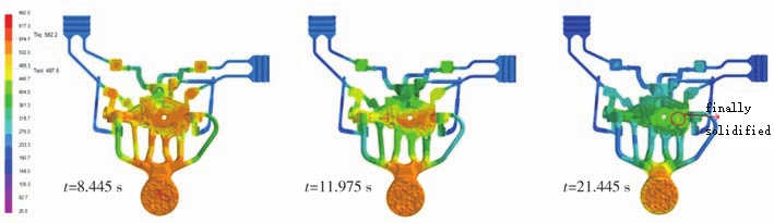
Die-casting machine is basic equipment for pressure casting of non-ferrous metals and their alloys and has a complex structure. Mold clamping mechanism consists of a mold plate and a machine hinge, and is the key mechanism of die-casting machine. Each die-casting production cycle is accompanied by an opening and closing action of mold closing mechanism. Mold clamping and mold opening of mold closing mechanism mainly uses oil cylinder to push hinge system. Structure is shown in Figure 1. Hinge system rapidly expands thrust of oil cylinder to promote movement of mold plate. Machine hinge system is a typical multi-link mechanism. Unreasonable design of toggle rod (connecting rod) size will lead to insufficient expansion ratio of mold closing mechanism, large impact during mold closing process, low mold life, long mold opening and clamping time, and low die-casting efficiency. To achieve a large clamping force, it is necessary to increase cylinder thrust, which requires high energy consumption. At present, design of die-casting machine hinges is mainly based on theoretical calculation methods. Since other complex structural parts in mold clamping mechanism and deformation effects of various parts of hinge system itself cannot be taken into account, calculation results have large errors, resulting in an unreasonable hinge structure design. Repeated design and manufacturing lead to long R&D cycles and high costs. Collaborative application of digital modeling, finite element method and kinematic simulation technology provides new solutions for design of die-casting machine hinges. Through numerical simulation technology, not only quantitative design of performance can be achieved, but also optimal design can be achieved, significantly shortening research and development cycle of hinge system and saving costs. In response to actual problems reported by enterprise that large die-casting machine with a clamping force of 25,000kN has a large oil cylinder, high energy consumption, is accompanied by high abnormal noise during each mold opening and closing process, we carried out defect cause analysis and optimized design of hinge system based on numerical simulation methods machine hinge analysis based on numerical simulation methods to increase stroke of movable mold base plate, while minimizing stroke of oil cylinder, achieve smooth mold plate movement without pauses and noise during mold opening and closing process.
Graphical results
Establish a 3D assembly model of die-casting machine’s mold clamping mechanism with a clamping force of 25000kN. Materials of components are QT500 and No. 45 steel respectively. Physical property parameters of materials are shown in Table 1. Discretize components in assembly model respectively, define contact relationship and friction factor and other parameters between connecting parts, apply corresponding load of 25000kN, and constrain displacement freedom of fixed mold base plate. Established mold clamping mechanism model is shown in Figure 2.
Figure 1 Schematic diagram of machine hinge system
1. Mold clamping cylinder 2. Tail plate 3. Hook hinge 4. Cross head 5. Small hinge 6. Long hinge 7. Moving mold base plate
Material
Density/(kg*m-3)
Elastic modulus/MPa
Poisson’s ratio
Yield strength/MPa
Tensile strength/MPa
QT500
7000
1.62*100000
0.292
320
500
45 # steel
7890
2.09*100000
0.269
355
600
Table 1 Material physical performance parameters
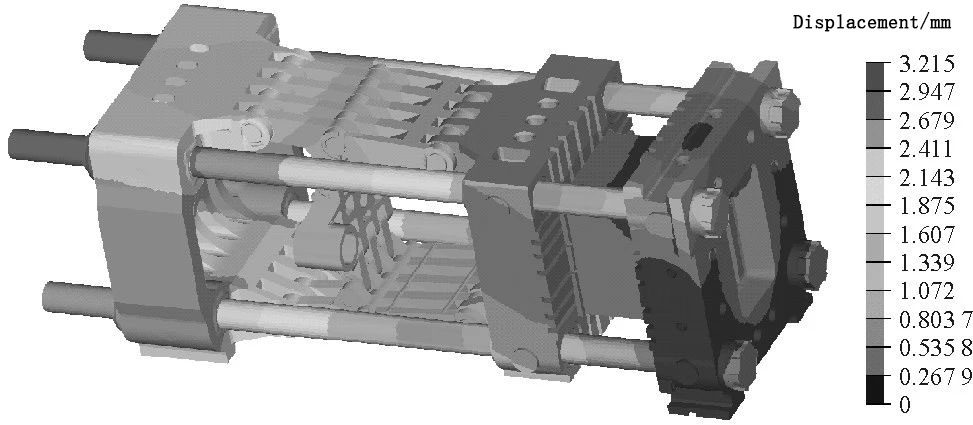
Figure 2 Mold clamping mechanism model
Figure 3 Displacement cloud diagram of mold clamping mechanism It can be seen that maximum displacement of mold clamping mechanism is 3.22mm, which is located at the end of Gorin column near tail plate. Ignoring local stress at unit contact boundary, maximum stress of mold clamping mechanism is 118MPa, located inside connection between hook hinge and tail plate, which is far less than yield strength of material (320MPa), so the overall structure of mold clamping mechanism can meet strength design requirements.
Figure 4 Stress cloud diagram of mold clamping mechanism
Component/Subsystem
Tailgate
Hinge system
Fixed and movable mold base plates and molds
Corinthians
horizontal
vertical
Vertical 1
horizontal
Vertical 2
horizontal
vertical
Load/kN
25000
910
910
25000
875
25000
875
25000
Displacement/mm
0.298
0.345
0.923
0.986
3.42
0.961
0.178
2.63
StiffnesskN/mm
83893
2638
986
25355
256
26015
4916
9506
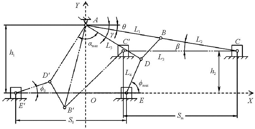
Table 2 Stiffness of mold clamping mechanism components and subsystems Figure 5 shows hinge system of a 25000kN die-casting machine. It is a typical double-bent toggle structure with 5 hinges. Cross head, small hinge, hook hinge and long hinge are used as toggle levers respectively. Toggle levers are connected by rotating shafts. A, B, C, D and E are hinge points between hook hinge and tail plate, long hinge and hook hinge, movable mold base plate and hook hinge, hook hinge and small hinge, small hinge and cross head in upper half hinge. According to structure and working mechanism of hinge system, its motion geometric relationship is established, as shown in Figure 5.
Figure 5 Schematic diagram of motion relationship of machine hinge system
Figure 6 Mold clamping force calculation flow chart
Figure 7 Kinematics simulation model of machine hinge system
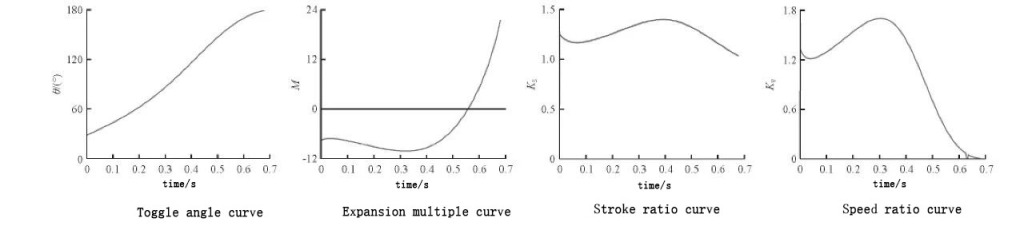
Figure 8 Kinematics simulation results of the machine hinge system Expansion ratio, stroke ratio and speed ratio are all key parameters of hinge system. Goal of optimized design of machine hinge system is to have a large expansion ratio and stroke ratio in clamping state. During expansion of machine hinge system, speed in the middle of stroke is relatively high, speed in initial and final stages of stroke (close to mold clamping state) is relatively small. Machine hinge system is a typical multi-link mechanism. Without changing number of toggle levers, hinged positions of toggle levers and movable seat plate and tail plate, main influencing factors of system performance are length and stiffness of each toggle lever. Therefore, plane coordinate values of the three toggle lever hinge points in Figure 5, B, D, and E, are used as design variables, as shown in Table 3. Length of each toggle lever is controlled by design variables to optimize design of machine hinge system.
Variable name
DV1
DV2
DV3
DV4
DV5
DV6
Variable coordinates
Bx
By
Dx
Dy
Ex
Ey
Original value
1169.840
275.968
1031.287
552.829
662.800
460.000
Table 3 Design variable table
Design variable
Initial value
Stroke ratio
Expansion multiple
Speed ratio
DV1
1169.840
-0.000083
0.11
-0.001
DV2
275.968
0
-40.28
-0.0019
DV3
1031.287
0.00082
-0.079
0.00097
DV4
552.829
0.0021
-349.81
0.00035
DV5
662.800
0.000049
48.99
0.00018
DV6
460.000
-0.00032
-150.16
0.0012
Table 4 Sensitivity of design variables to design goals
Variable name
DV1
DV2
DV3
DV4
DV5
DV6
Expansion multiple
Stroke ratio
Original value
1169.840
275.968
1031.287
552.829
662.800
460.000
21.45
1.03
Optimization value
1146.443
264.929
1072.539
536.244
696.000
446.200
24.57
1.08
Table 5 Coordinates of toggle joint hinge points
Figure 9 Comparison curve of performance indicators of machine hinge system before and after optimization
In conclusion
(1) Deformation of toggle bar has a great impact on performance of machine hinge system. Influence of toggle bar deformation should be considered in design process of machine hinge system. (2) Calculate stiffness and strength of mold clamping mechanism through finite element method. When mold clamping force is 25000kN, local maximum stress of mold clamping mechanism is 118MPa, and the overall structure meets strength design requirements. (3) Considering influence of toggle deformation, based on rigid-flexible multi-body dynamics modeling and kinematic simulation calculations, force expansion multiple of hinge system is 21.45, which is close to actual test result of 21.40, and numerical model is reliable. (4) By optimizing spatial position of toggle joint hinge point of die-casting machine, hinge system can be optimized. After optimized design, force expansion factor of hinge system reaches 24.57, and stroke ratio is 1.08, which are 14.5% and 4.85% higher than before optimization respectively. During mold clamping process, impact on driving cylinder, hinge system, mold plate and mold is smaller.
For die-casting sites, automated and intelligent equipment have been used in production. However, how to ensure long-term stable production of these equipments, main task is to “maintain stability”, find out fluctuation factors in each link, use feasible and reliable methods to restore them to a stable state, “seeking stability first, then seeking improvement”, this work is repeated over and over again, there is no one-and-done solution, and there are no shortcuts. Product quality problems encountered at die-casting site may not be caused by one factor. When solving problem, multiple factors need to be integrated to deal with it, so that product can be produced efficiently, with high quality and stably. This article uses Six Management Factors (5M1E) to find out factors that may cause instability on die-casting process site, controls and improves these factors, proposes a strategy for maintaining stability of die-casting process. Die casting is a technology that produces parts with complex shapes with high automation and high efficiency. Parts produced by this technology have advantages of good density, high precision, small machining allowance, and excellent mechanical properties. They have been widely used in automobiles, mechanical equipment and other fields. In high-pressure casting industry, problems of pores, shrinkage cavities, and internal cold isolation in die-casting parts have always troubled die-casting people. Although there are prescribed standards for requirements for porosity and shrinkage, quality of die-casting parts is often good and bad due to various uncertain fluctuation factors in production process, which leads to unstable quality of die-casting parts. Due to rapid filling and forming, a certain amount of gas will remain inside die casting due to various factors. With emergence of advanced process technologies such as vacuum die-casting, oxygenated die-casting, and local extrusion, internal quality of die-casting parts has been improved to a certain extent, but existence of pores, shrinkage cavities, and cold insulation is still unavoidable. Even so, problems such as pores, shrinkage cavities, and cold insulation can be controlled within a certain range. Die-casting actually refers to collective name of the three elements of die-casting machine, die-casting alloy and die-casting mold. Die-casting process integrates and applies these three elements to production. Hoda Dini et al. studied effect of die-casting pressure on deformation and residual stress of die-cast AZ91D alloy castings. Research results show that die-casting pressure has a greater impact on deformation and residual stress of castings. Increasing die-casting pressure will reduce deformation of casting, but residual stress on the surface will increase. Many scholars have studied issues such as temperature field distribution and temperature gradient of molds and die-casting parts during die-casting process. P.Sharifi et al. conducted experiments to study influence of process parameters on castings during die-casting process. Results show that among many process parameters, punch speed has the greatest impact on porosity of castings. However, for some special alloys, slow injection speed has a greater impact. Nowadays, more and more companies are using Internet big data to monitor die-casting process in real time and adjust die-casting parameters. Formulation of die-casting process plan is a very important step. Rationality of process directly affects quality of castings and subsequent processing and production links. Quality of die-casting parts is often related to many factors. Reasonable and effective control of quality of die-casting parts requires comprehensive consideration of many factors. Long-term stability of die-casting quality is very important to company’s costs and profits. However, complexity of die-casting site makes it more difficult to control and manage quality of die-casting parts. Based on this, a die-casting process stability maintenance strategy based on six factors of on-site management (5M1E) was proposed to systematically solve problem of quality management of die-casting parts at die-casting site.
1. Die-casting site problems and measures
When quality fluctuations occur in die-casting parts, on-site technicians often first choose to adjust process parameters instead of finding root cause. For example: when internal defects occur, change high-speed switching point, increase fast injection speed, and increase pressure opening; ② When mold is pulled, increase release agent spray volume or lengthen spray time; ③ When punch is stuck, increase amount of lubricant; ④ When temperature of aluminum liquid in holding furnace is not enough, use a flamethrower to bake on liquid surface of pouring port. Each of above inappropriate adjustments may bring about a 3% defective rate, and more than three inappropriate adjustments may bring about a defective rate of more than 10%. Therefore, we should not think too deeply about problem, but find cause in detail for each problem, use appropriate methods to fundamentally solve problem and maintain it. That’s kind of conviction our field technicians need to have.
2. Die-casting site stability maintenance factors
When equipment, molds, and process technology conditions have met quality requirements of die-casting parts, the most critical thing at die-casting site is to control stability of comprehensive factors. For example: comprehensive condition of equipment and mold, quality of compressed air and range of pressure fluctuations, insulation effect and temperature fluctuation range of alloy liquid, mold temperature and ambient temperature. Only when comprehensive factors are stable can quality of die castings be relatively stable.
2.1 Six factors of on-site management (5M1E)
Six factors of on-site management refer to Man, Machine, Material, Method, Measurement and Environment, referred to as 5M1E. As shown in Figure 1 fishbone diagram.
Figure 1 Fishbone diagram
2.1.1 Human factors
People are leader in die-casting scene and are the first of all factors. Including production safety, all work surrounding production activities is decided by people. Product quality will always fluctuate. Use management tools to analyze and solve problems, control fluctuations in each link to a minimum, and reduce the rate of defective products. All of this still relies on people.
2.1.2 Machine factors
Machine refers to working machine, mold and supporting auxiliary equipment. Due to importance of mold in die-casting process, it will be analyzed as a separate factor below. Capability of machinery and equipment is decisive factor in production and manufacturing capabilities, so the higher high-end equipment, the higher maintenance requirements. During production arrangement process, machines and equipment suitable for different products are selected. Carry out daily inspections so that problems can be discovered and repaired promptly. Carry out regular maintenance or scheduled maintenance to ensure that equipment is in good condition and has stable performance. It is strictly prohibited to dismantle one thing to make up the other, and keep equipment intact. Problems that are easily overlooked at die-casting production site: ① Impact of poor matching of injection rod connection part on quality of die-casting parts; ② Impact of unstable feeding of feeder on quality of die-casting parts. As shown in Table 1 (density of liquid aluminum 2.64g/cm³).
Injection head diameter/mm
Cross-sectional area of injection head/cm2
10mm/thickness handle weight/g
Allowable fluctuation range product of material handle thickness/mm (empirical data)
60
28.26
74.61
1.Ф80+3 2.Ф90 soil 4 3. It also depends on weight of die casting. The lighter casting, the worse its ability to resist fluctuations.
70
38.47
101.56
80
50.24
132.63
90
63.59
167.88
100
78.5
207.24
Table 1 Relationship between material handle thickness and weight As mentioned in Table 1, because most of our current die-casting machines use position triggering to set high-speed switching point, if pouring machine is unstable (thickness of material handle is too different), it can directly lead to a change in actual starting point of high-speed filling, affecting stability of die casting quality. Assume that when high-speed switching point has been set at a certain position value, as shown in Figure 2, Figure 3, and Figure 4, flow channel is full and aluminum liquid just reaches gate. This is ideal high-speed switching point, as shown in Figure 2.
Figure 2 Normal state when pouring volume is stable Some molten aluminum has entered mold cavity through inner runner during slow injection process, which can easily form a cold isolation inside casting, as shown in Figure 3.
Figure 3 Abnormal state when pouring amount is too much Liquid aluminum failed to fill flow channel, and gas was trapped in the front end, causing pores inside casting, as shown in Figure 4.
Figure 4 Abnormal state when pouring amount is too small Unstable spray volume and atomization effect of sprayer can also affect quality of die castings. Large fluctuations in compressed air pressure, normal air pressure should be controlled at 5.5 ~ 6.5 kg/c㎡, which is very important; large fluctuations in air pressure cause release agent pressure to also fluctuate significantly. Large fluctuations in air pressure and water pressure cause release agent spray volume and atomization effect to change with changes in air pressure. Mold temperature and release lubrication effect also change accordingly, and product quality also fluctuates. Air humidity in most areas of southern my country is relatively high in summer, and a large amount of emulsified water will be produced in compressed air. This emulsified water will be sprayed onto mold cavity with air flow, which will increase number of pores and cold insulation inside die casting, and will also cause spots and other undesirable phenomena to appear on the surface of die casting. This is an undesirable factor that many people ignore. Therefore, automatic drain valves should be installed at the bottom of gas storage tank and the lowest point of main pipe to automatically drain water regularly to minimize moisture in compressed air.
2.1.3 Mold factors
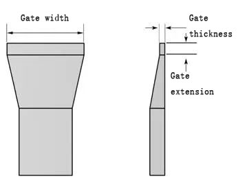
On the premise that equipment meets on-site conditions, condition of die-casting mold has main influence on quality of die-casting parts. During die-casting production process, on-site personnel often spend the most time and energy on mold. Therefore, daily maintenance of mold is very important. Following points should be paid attention to. (1) Ensure that parting surface is intact. If parting surface is not well matched, air edges or flying materials may easily occur. Flying materials will cause pressure loss in cavity and no material feeding, causing large pores and large areas of looseness inside die casting. For quality and safety, strict control is required. (2) Maintenance of size and shape of gate. At die-casting production site, it is very important to control thickness, width and extension of gate. During production process, as gate continues to be eroded, width and thickness of gate continue to increase, extension of gate becomes shorter and shorter, internal defect rate of die casting will become higher and higher. Above phenomenon is called runner erosion, which is an inevitable phenomenon during die-casting production process. Adverse consequences caused by sprue erosion are common and often ignored. Due to erosion, width and thickness of gate are increased, which increases cross-sectional area of gate. Consequences of changes in process parameters are as follows: ① Filling resistance decreases, flow rate of ingate changes accordingly, which also changes filling time; ② Filling time is shortened, which increases pressure of gas in cavity and increases exhaust resistance; ③ Exhaust speed changes accordingly, part of gas is not discharged in time and remains inside die casting; ④ Gas that is not discharged in time remains to form pores inside die casting, distribution gradually evolves from regular to irregular. As erosion continues, cold gaps will gradually appear inside casting. Therefore, it is necessary to control dimensional changes in gate width, thickness and gate extension within a reasonable range. Judging from empirical data, extension of gate should be 1 to 2 times thickness of gate. Its main function is to crush gas in molten aluminum in flow channel during high-speed filling to avoid formation of large pores in casting. It is also helpful in reducing cold shut, as shown in Figure 5.
Figure 5 Gate size and gate extension (3) Cooling water path should be kept clean and smooth and water pressure should be stable. Mold temperature control is an effective means to stabilize quality of die castings. Without cooperation of a mold temperature controller, integrity and effectiveness of mold cooling system is also a link that must be controlled in die-casting production process. If cooling effect is not good and mold temperature is too high (more than 250℃), release agent will be difficult to effectively adhere due to vapor rebound, resulting in shrinkage holes inside die casting and localized aluminum sticking on the surface, etc., which will also affect production efficiency. Excessive cooling will cause mold temperature to be low (below 180 ℃), which will cause release agent to be unable to effectively adhere, affecting demoulding effect, water will not evaporate normally, which will cause undesirable phenomena such as pores, cold insulation, and local cold material accumulation inside die casting. There are several problems that are easily overlooked at die-casting production site. (1) Impact of poor coordination between sprue sleeve and melting cup on quality of die castings. (2) Impact of clogging of exhaust groove of exhaust block on quality of die castings. At production site, especially in old molds, this situation often occurs: there are many places on parting surface that can be vented, but only vent grooves and vent blocks are blocked and cannot be vented normally. This phenomenon is often overlooked, but it actually changes exhaust sequence. Filling sequence and exhaust sequence should go in opposite directions, must not go opposite to each other. This is also one of factors that mistakenly believe that mold exhaust effect is very good, but porosity of die castings is always high. (3) Impact of cooling water dripping on quality of die castings. Cooling water dripping is a common problem at die-casting site. It may seem like a small matter, but in fact it hides major hidden dangers: ① Water leaking into mold cavity and melting cup not only causes a local temperature drop, but also causes a drop in local temperature when water encounters molten aluminum. It will quickly vaporize to produce a large amount of hydrogen, which will be absorbed by aluminum liquid and filled into mold cavity. This is also one of factors causing high porosity of die castings; ② Water leaking from cooling holes, centralized distributors, etc. to mold base cannot be underestimated. When amount of water leakage is large, it will lower mold base temperature and make it difficult to maintain mold core temperature. It will also enter mold cavity from fitting gaps. This is also one of factors causing high porosity rate of die castings. (4) Impact of cylinder oil leakage on quality of die castings. Oil leakage from oil cylinder will not only cause same pore problems as water leakage, but also cause greater oil consumption, directly increase production costs, leave hidden dangers such as safety and environmental protection.
2.1.4 Material factors
Materials mainly refer to raw materials and auxiliary materials. Raw materials that affect quality of die castings (mainly pores) mainly include following factors.
(1) Internal density of aluminum ingots. According to experience, aluminum ingots with neat fractures and fine and uniform cross-section crystals can be judged as good materials, while those with coarse fracture surface crystals can easily cause internal pores in die casting, as shown in Figure 6. Cross-section of aluminum ingot on the left has thick crystals, while cross-section of right part has fine and uniform crystals.
Figure 6 Internal quality of parts (2) Melting temperature: Temperature of molten aluminum in insulation chamber of central melting furnace should be controlled at 720~740℃. If temperature is too high, it will easily cause material crystals to become coarse, causing pores inside die casting. If temperature is too low, it will be difficult to maintain accumulated temperature drop in each link during turnover process. (3) Insulation temperature: Insulation temperature in holding furnace should be maintained at 650 ~ 680 ℃. For small die castings, when material temperature is lower than 650 ℃ (especially lower than 640 ℃), pores and cold insulation are likely to occur inside die castings. . Problems that are easily overlooked at die-casting production site: whether temperature of melting furnace insulation pool reaches above 720℃; whether transfer process causes too much heat loss; whether insulation furnace has sufficient insulation and heating capabilities. Whether holding furnace has sufficient insulation and heating capabilities, pay attention to following points: whether seal between furnace body and furnace cover is intact; whether feeding trough has a cover seal; whether sealing between feeding trough and furnace body is intact. Negligence in each of above steps will cause heat energy loss and result in low aluminum pouring temperature. (4) Auxiliary materials: Auxiliary materials include refining agents, slag breakers, release agents, punch oil (particles), etc. Quality of these auxiliary materials, or whether they are used timely and effectively, will also directly affect quality of die castings.
2.1.5 Legal factors
Dharma refers to decision-making, methods and techniques. This is one of management tools that runs through the entire process of production activities. If there is a problem in each of four factors above, you can use this tool to analyze it, find out reasons, formulate improvement plans and implementation measures, then follow up and summarize effects. This cycle continues, but you need to pay attention to following points. (1) For production safety, equipment management and maintenance work, daily inspection process and production process must meet response speed and countermeasures for discovered problems, ensure that equipment operating conditions meet needs of production technology and technology. This is an unshakable premise. (2) For use, maintenance and upkeep of molds before and after production, during production process, analyze potential failure modes (FMEA), formulate a storage plan for wearing parts, formulate and implement a spare mold plan based on purchase volume. (3) Formulate, implement and review die-casting process, and conduct daily inspections to ensure seriousness of process card. (4) Control of temperature of molten aluminum is an unavoidable issue, and lower limit of 650℃ is a red line that cannot be exceeded. Most technicians at production site only focus on data of fast injection and boosting parts. In fact, improper setting of slow injection speed has a great impact on quality of castings. Problems that are easily overlooked at die-casting production site: impact of slow injection speed on quality of die-casting parts; difference between slow-speed filling state theory and practice. Slow injection is front part of fast injection. Theoretically, function of slow injection is to fill flow channel with molten aluminum and push it to vicinity of gate. As can be seen from Figure 7, this is not the case. In fact, when a small amount of front peak of aluminum liquid has crossed inner runner, runner is not completely filled and is also mixed with gas. This phenomenon becomes more serious the faster injection speed, the more serious it is. Therefore, it is important to choose a suitable slow injection speed.
Figure 7 Slow filling theoretical calculation and actual state Air blowing is an effective method to remove moisture residue, but it is not a good thing to blow too much air from sprayer and for too long. Over-reliance on air blowing not only loses mold temperature, but also wastes resources. The lower mold temperature, the more moisture remains, and the more it needs to be solved by blowing air, and so on. Therefore, concentration of release agent should be as high as possible to enhance lubrication of mold while reducing amount of water sprayed out.
2.1.6 Environmental factors
Environmental factors refer to environmental factors, which can affect all above links, mainly safety, which is also a factor that cannot be ignored. Changes in ambient temperature will affect personnel’s emotions, pose safety risks, also affect equipment accuracy and performance. Equipment failure rates are always higher in summer. For precision cutting processes and inspection processes, ambient temperature has a great impact on dimensional accuracy, and some small details are often not paid attention to. Problems that are easily overlooked at die-casting production sites: For production sites without mold temperature machines, release agent concentration, spray time, and cooling water flow must be adjusted immediately according to ambient temperature changes in summer and winter to keep mold temperature within a suitable and relatively stable temperature difference range. For example, if ambient temperature is high in summer, release agent can be used with a lower concentration and an appropriately long spray time. When ambient temperature is low in winter, a higher concentration of release agent can be used and spraying time should be shortened appropriately. According to ambient temperature changes in summer and winter, cooling water flow rate is increased in summer and reduced in winter. Clean cooling water channels regularly to maintain cooling effect. For areas with high relative air humidity, when relative air humidity reaches 90% or higher, in addition to fact that die castings are prone to blackening and moldiness, gas generated by air compressor will also contain a large amount of emulsified water, which can cause pores in die castings. High humidity seasons can easily cause electrical failures. Equipment that has been suspended from production should be kept powered on regularly. In particular, weak current control system can be powered on to keep it dry by self-heating.
2.1.7 Measurement factors
Measurement is quality inspection, which mainly refers to measurement tools, measurement methods, trained and authorized measurers. In modern production process, testing is an important factor. Without testing and control, it is difficult to ensure product quality. When measuring and controlling, you need to pay attention to: ① Whether responsible person is designated; ② Whether prescribed measuring tools are used; ③ Whether it is at designated measuring point; ④ whether correct measurement method is used; ⑤ Whether measurements are carried out at a certain frequency; ⑥ whether there are records. Improving ease of operation of measuring instruments and ensuring measurement accuracy is very helpful for product quality control.
3. Application examples of die-casting process stability maintenance strategy
3.1 Release agent maintains stability
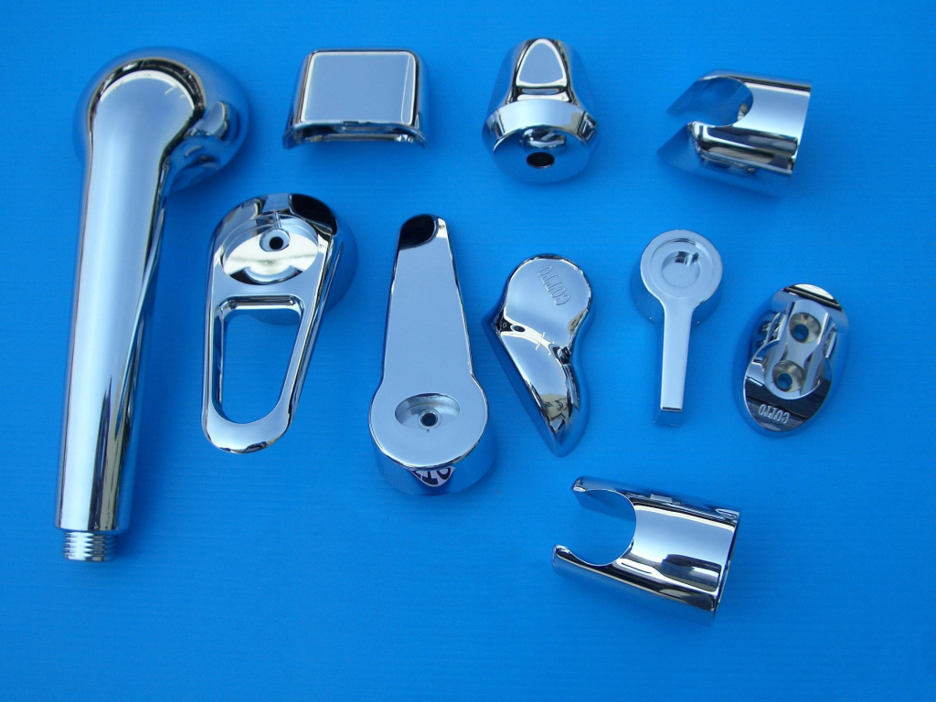
Application examples of separately proportioned release agents. For valve body shown in Figures 8 and 9, due to small draft angle of individual holes, only 5027 release agent can be used, and proportion concentration is too high (1:160 ~180), so that product quality is better and stability of on-site production can be achieved.
Figure 8 Draft angle of individual holes in valve body
Figure 9 Valve body and valve port surface quality requirements are high
3.2 Maintaining stable dimensions of gate
3.8JB flame distributor is shown in Figure 10. Product has a diameter of 140 mm and a height of 28 mm. It is required that there should be no pores, micro-spots, flow marks, chromatic aberration, etc. after large-area mirror processing on the surface. Gate size: The two points in the middle are 18mm * 1.2mm (limit 1.4mm), the two points on both sides are 16mm * 1.1mm (limit 1.3 mm), punch diameter is 55 mm, injection head area ratio of gate size is 1:30.3, and fast injection speed is set to 2.3m/s (actual speed 1.9~2m/s). By adopting such a gate size, product will have better quality and achieve stable production.
Figure 10 3.8JB flame distributor Under premise that set conditions remain unchanged, when actual speed of fast injection reaches more than 2m/s, pores and micro-spots will appear on processed surface.
3.3 Maintain stability of mold parting surface
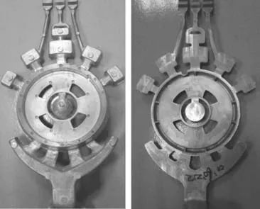
368B type flame distributor is shown in Figure 11. This piece has 7 core-pulling die-casting parts. It is required that there are no pores, micro-spots, flow marks, chromatic aberration, etc. after large-area mirror processing on the surface. During die-casting production process of this part, if cracks appear on parting surface, pores will appear on machined surface of die-casting part, and this has been verified many times. Therefore, keeping parting surface intact, die-casting parts without gaps, and keeping size of ingate within established range are focus of maintenance work for this set of molds.
Figure 11 Type 368B flame distributor
4 Conclusion
Among six major factors, according to analysis results of last five major factors, factors affecting production are wide-ranging, diverse, changing at any time, and unpredictable. But when undesirable factors occur, key is whether problem can be discovered or taken seriously in time, whether it can be dealt with in time, how to deal with it, who will deal with it, what results will be after treatment, etc. All spearheads here point to people, so talent is core element among six elements. For die-casting site, main job is to “maintain stability”, find out fluctuation factors in each link, use feasible and reliable methods to restore it to a stable state. “Seek stability first, then seek improvement.” This work is repeated, there is no one-time solution, and there are no shortcuts either. A product problem at die-casting site may be caused by joint action of several of six elements. When solving problem, product problem is not solved by just solving one of elements, but by integrating six elements and solving it comprehensively. Therefore, product problems can be solved efficiently and with high quality according to “stability maintenance” strategy of die-casting process.
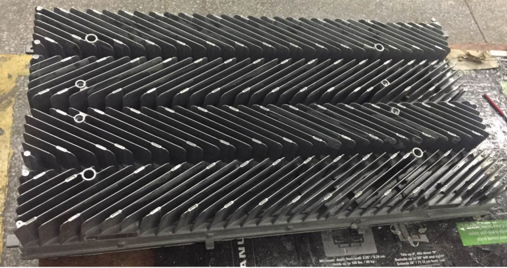
Effect of heat treatment on mechanical and thermal conductivity properties of die-cast aluminum alloy ZL102 was studied using microstructure characterization, mechanical and thermal conductivity testing. Results show that physical phases in room temperature structure of die-cast aluminum alloy ZL102 include primary α (Al), aluminum-silicon eutectic structure, primary crystalline silicon and a small amount of intermetallic compounds. After solid solution treatment, silicon phase in die-cast aluminum alloy ZL102 fuses and spheroidizes; after aging treatment, fine point-like second phase precipitates on α (Al) matrix, and sphericity of silicon phase at grain boundary is further improved. Among three heat treatment states, aluminum alloy ZL102 has the highest mechanical properties after solution treatment, but the lowest thermal conductivity. In summary, aging treatment takes into account mechanical and thermal conductivity properties of alloy. At this time, tensile strength of alloy is 212MPa, elongation is 3.9%, and room temperature thermal conductivity is 142.7W/(m·K). With advent of 5G communication era, integration of electronic communication equipment and products is gradually increasing, and amount of heat generated per unit volume is also increasing. At this time, relevant materials and structures are required to have good thermal conductivity properties to ensure normal operation of equipment and products and extend their service life. Take 5G communication filter as an example. It has high power and high integration. In order to improve heat dissipation capacity, filter housing structure is usually designed with many irregular thin-walled heat sinks. For mass forming and manufacturing of this type of structural shells, die-casting process has significant efficiency and cost advantages. Density of metallic aluminum is only 1/3 of steel and iron, and it has huge potential for lightweighting. In recent years, it has been widely used in automobiles, communications, aerospace and other fields. Room temperature thermal conductivity of pure aluminum is approximately 237 W/(m·K), and it has excellent thermal conductivity. However, strength of pure aluminum is low. In actual production, some alloying elements are often added to improve its mechanical properties, and addition of alloying elements will have a certain impact on its thermal conductivity properties. Usually, alloying elements strengthen aluminum alloys in the form of solid solution atoms, intermediate phases or precipitation strengthening phases. However, whether it exists in the form of solid solution atoms or intermediate phases, it will bring a large number of vacancies, dislocations and other crystal defects to alloy, and precipitated phase will also cause lattice distortion in alloy. Existence of these defects increases probability of free electron scattering in alloy and reduces number of electrons for effective heat conduction, resulting in a reduction in thermal conductivity of alloy. In order to take into account mechanical and thermal conductivity properties of aluminum alloys, researchers have conducted in-depth research. Wen Cheng studied effects of 22 alloy elements on electrical and thermal conductivity of industrial pure aluminum and found that different elements have different effects. Addition of transition elements such as Mn, Cr, etc. will cause electrical and thermal conductivity of pure Al to decline rapidly, while Zn, Sr and rare earth metamorphic elements have less impact. Li Linjun found that different magnesium to silicon ratios have different effects on thermal conductivity of aluminum alloy 6063. When magnesium to silicon ratio is 1.5, alloy has the best thermal conductivity. Lumley et al. studied effects of alloy composition and heat treatment on thermal conductivity of Al-Si-Cu aluminum alloy die castings. Study showed that thermal conductivity of alloys with certain compositions can be increased by more than 60% through use of heat treatment. Kim et al. tested thermal diffusivity of Al-1Si and Al-9Si alloys under different heat treatment conditions, studied relationship between thermal diffusivity and silicon phase solid solution and precipitation, concluded that re-precipitation of dissolved silicon in solution-treated samples will increase thermal diffusivity of alloy. Choi et al. studied effect of mold temperature on thermal and mechanical properties of aluminum alloys and concluded that the higher mold temperature, the slower solidification rate of alloy. At this time, the larger silicon particles are, the better thermal properties of alloy are. After aging treatment, mechanical strength of alloys at different mold temperatures becomes similar. This article takes a 5G communication filter housing as an actual die-cast aluminum alloy ZL102 as research object, uses flash method to test thermal conductivity of alloy at different temperatures, changes microstructure of alloy through heat treatment to explore impact of alloy microstructure changes on mechanical and thermal conductivity properties, with a view to providing a reference for improving mechanical and thermal conductivity properties of aluminum alloy die castings in actual production.
01 Experimental procedure
1.1 Sample preparation
An actual die-cast product of a 5G communication filter housing was used as test piece. As shown in Figure 1a, die-cast piece weighs about 5.4kg and has an overall size of about 539mm * 410mm * 45mm. Die-casting part has a complex structure and shape. Wall thickness of main body is only about 2mm, while wall thickness at mounting lugs and other locations reaches 6mm. Sampling position for microstructure characterization, mechanical and thermal conductivity testing in test is shown in Figure 1b. Wall thickness at this position is wall thickness of main body of die casting, which is well representative and convenient for sampling. Chemical composition of aluminum alloy ZL102 measured by X-ray fluorescence spectrometer (XRF) is shown in Table 1. Mechanical properties tensile specimens were prepared by wire cutting, and dimensions were determined in accordance with national standard GB/T228.1-2010. At the same time, Φ4mm*1mm disc samples were wire-cut for testing thermal conductivity of alloy. Heat treatment of samples is divided into three control groups. One group is in die-cast state without heat treatment; second group undergoes solution treatment at 500℃*4h; and third group undergoes aging treatment at 200℃*3h based on second group.
Figure 1 Actual die-cast product of a 5G communication filter housing
1.2 Test methods
Metallographic samples were mechanically ground with 240#, 600#, 1200#, 1500#, and 2000# sandpaper in sequence, polished with diamond polishing agent, then used 95%H2O+2.5%HNO3+1.5%HCl+1%HF Keller’s reagent to corrode for 10~20s. Structural morphology was observed under a Leica DM2700M optical microscope (OM) and a JEOL 6301F scanning electron microscope (SEM). Instron 5967 electronic universal testing machine was used to conduct room temperature tensile test. Tensile speed was 2mm/min. Mechanical property test data was average of 5 effective specimens. According to physical laws of heat conduction, temperature field inside object will change with time during heat conduction, which makes it difficult to directly measure thermal conductivity. In this paper, based on measuring density, specific heat capacity and thermal diffusion coefficient of alloy, thermal conductivity of alloy is calculated using equation (1) λ=αρCρ (1) In formula: λ is thermal conductivity of sample to be measured, unit is W/(m·K); α is thermal diffusion coefficient of sample to be measured, unit is mm2/s; ρ is density of sample to be measured, unit is g /cm3; Cρ is specific heat capacity of sample being tested, in J/(g·K). LFA457 laser thermal conductivity meter was used to measure thermal diffusion coefficient of sample, specific heat capacity was measured using TA-DSC2500 differential scanning calorimetry, and Archimedean drainage method was used to measure density of sample.
02 Aluminum alloy ZL102 die casting structure
Filter housing is die-cast from aluminum alloy ZL102. According to Table 1, silicon content in alloy is 12.8% (mass fraction, same below), which is close to eutectic composition of aluminum-silicon binary alloy (Si content of eutectic composition point in Al-Si binary equilibrium phase diagram is 12.6%). When alloy solidifies, eutectic reaction L→α(Al) + β(Si) mainly occurs, forming a large amount of α(Al) + Si eutectic structure. However, due to high cooling rate of alloy during die-casting process and solidification process away from equilibrium, phases present in die-casting structure of aluminum alloy ZL102 at room temperature include primary α (Al), aluminum-silicon eutectic structure, primary crystal silicon and a small amount of intermetallic compounds.. Figure 2 shows surface and core microstructure of die-casting obtained by OM. Gray-white matrix is primary α (Al), and there are a large number of gray-black alternating aluminum-silicon eutectic structures distributed between matrix, as well as needle-shaped / lath-shaped primary crystal silicon. Comparing Figure 2a and Figure 2b, surface structure is finer and more uniform. This is because surface layer of die casting is in direct contact with mold wall during forming. Alloy has a high cooling rate and a high degree of supercooling, making grains in surface structure finer and more uniform. In addition, a small amount of large gray polygonal structures were found in core structure of die casting, as shown in Figure 2b. Since iron content in alloy composition is slightly higher, it is initially judged to be an iron-containing phase. Alloy phase composition was tested using X-ray diffraction (XRD), with a scanning range of 10°~90° and a scanning speed of 4°/min. Test results were imported into MDI Jade 6 for analysis. Results are shown in Figure 3. It can be seen from XRD test results that there are only α (Al) and Si phases in alloy, and no iron-containing intermetallic compounds were detected. Reason for above situation may be that content of intermetallic compounds in alloy is low, resulting in XRD not detecting detected.
Si
Mg
Fe
Mn
Cu
Zn
Ti
Al
12.8
0.019
0.915
0.184
0.224
0.127
0.001
magin
Table 1 Chemical composition of aluminum alloy ZL102 wB/%
Figure 2 Microstructure of aluminum alloy ZL102 die casting
Figure 3 XRD pattern of die-cast aluminum alloy ZL102 SEM was used to further analyze the above polygonal phases, as shown in Figure 4. Based on energy spectrometer (EDS) results (Table 2), it is speculated that it is a complex AiSiFeMn quaternary intermetallic compound. Based on some literature such as Yuan, Wang, etc., it was determined that phase is α-Al 15 (Mn, Fe)3Si2. This phase is further evolved by adding Mn element to β-Al5FeSi phase. When β-Al5FeSi phase is formed, some Mn atoms take away positions occupied by Fe atoms in β phase, which is equivalent to Mn atoms partially replacing Fe atoms, thus forming AlSiFeMn quaternary composite phase.
Figure 4 SEM image of polygonal phase
Element
Al
Si
Fe
Mn
Cr
Quality score
54.63
13.38
21.79
6.52
3.67
Atomic fraction
65.72
15.47
12.67
3.85
2.29
Table 2 EDS analysis results of point P in Figure 4 %
03 Effect of heat treatment on die casting structure
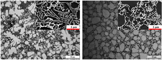
Figure 5 compares and analyzes aluminum alloy ZL102 die-casting structure before and after heat treatment. It can be seen that primary α (Al) changes little before and after heat treatment, and dendrite orientation has no obvious rules, while morphology and distribution of silicon phase have changed significantly. Silicon phase in die-cast structure shows a needle-like/lath-like distribution, which seriously splits α(Al) matrix; after solid solution treatment, silicon element originally dissolved into α(Al) matrix in solid solution stage precipitates, showing a fine point-like shape on α-Al matrix, while silicon phase at grain boundary is more rounded and sphericity is further improved. For polygonal AiSiFeMn quaternary intermetallic compound that appears in die-casting structure, its morphology does not change significantly during solution and aging treatment processes. It is speculated that reason is that solution treatment temperature in this article is not sufficient to dissolve it into α(Al) matrix. It can also be seen from Figure 5 that there are a certain number of pores distributed in die-casting structure. Pores in structure have a tendency to increase after solution treatment, but pores do not expand further with continued aging treatment.
Figure 5 Comparative analysis of die-cast, solid solution and aging structures
04 Effect of heat treatment on mechanical properties and thermal conductivity
Mechanical properties of die-cast aluminum alloy ZL102 under different heat treatment processes are shown in Figure 6. It can be seen that in terms of strength and elongation, solution-treated sample is better than die-cast and aging-treated sample. Its tensile strength and elongation are 222.8MPa and 6.1% respectively. Compared with die-cast state, tensile strength has increased by 9.2%, and elongation has been significantly improved, increasing by 205 %, while mechanical properties of aged specimens are in the middle. Analyzing reasons, although there have been studies that ordinary die castings are not suitable for heat treatment due to existence of pores, and aluminum alloy ZL102 is a non-heat treatment strengthened alloy. However, fusing and spheroidization of silicon phase during solid solution treatment process significantly improves its splitting effect on α (Al) matrix, reduces stress concentration generated around alloy when it is loaded, is conducive to improvement of alloy strength and elongation. After further aging treatment, mechanical properties of alloy have declined to a certain extent compared to solid solution state. Reason is that silicon phase precipitated in α (Al) grain boundaries and solid solution further aggregates and grows, causing coarsening, which damages mechanical properties of alloy, no aging strengthening phase precipitates during aging process of alloy.
Figure 6 Effect of heat treatment on mechanical properties of die-cast aluminum alloy ZL102 Figure 7 shows influence of different temperatures and heat treatment processes on thermal conductivity of die-cast aluminum alloy ZL102 measured in experiment. First of all, it can be seen that thermal conductivity of alloy in three states of die-casting, solid solution and aging increases with increase of temperature. From room temperature to 300℃, it shows a trend of rapid growth first and then slow growth. This changing trend is mainly related to thermal conductivity mechanism of alloys. For general metals, thermal conductivity consists of electronic thermal conductivity and phonon thermal conductivity. Correspondingly, thermal resistance is also divided into electronic thermal resistance and phonon thermal resistance. Electronic thermal resistance is caused by electrons being scattered by various media and consists of electron-phonon scattering and electron-defect scattering. Phonon thermal resistance is also determined by two processes: one is collision between phonons caused by nonlinear vibration of crystal lattice; the other is collision between phonons and defects in solid. When temperature is low, vibration amplitude of atoms on crystal lattice is very small, and contribution of phonons to thermal conductivity is small. Thermal conductivity is dominated by electrons. At this time, thermal conductivity of alloy is mainly determined by interaction between electrons and defects. Number of internal defects in alloy basically does not change with temperature changes in low-temperature region, and movement rate of electrons basically remains unchanged whether in the high-temperature or low-temperature region. At this time, mean free path of electrons can be approximately considered to be a constant. At this time, thermal conductivity of alloy is mainly determined by specific heat, and specific heat has a linear relationship with temperature. Therefore, thermal conductivity of alloy in three heat treatment states increases rapidly with increase of temperature at the beginning. As temperature continues to rise, vibration of atoms in alloy under three heat treatment states slowly intensifies. At this time, scattering effect of phonons on electrons begins to increase, probability of electrons being scattered increases, and mean free path of electrons begins to decrease, which causes thermal conductivity of alloy to slowly increase as temperature continues to increase.
Figure 7 Effect of temperature and heat treatment process on die-cast aluminum alloy ZL102 Effect of thermal conductivity Comparing thermal conductivity of alloys in three heat treatment states in Figure 7, it can be seen that die-cast alloy has the highest thermal conductivity at different temperatures. That is, solution and aging treatment processes in this article cannot improve thermal conductivity of die-cast aluminum alloy ZL102, but instead reduce thermal conductivity of alloy. Analysis of reasons shows that there are a large number of solid solution atoms in the sample after solution treatment, which causes lattice distortion, resulting in an increase in crystal defects in alloy, an increase in probability of electrons being scattered, a decrease in mean free path of electrons, and a significant reduction in thermal conductivity of alloy. After aging treatment, thermal conductivity of alloy recovers somewhat compared to solid solution state. This is because second phase precipitates during aging treatment, which reduces solid solubility of alloy and reduces degree of lattice distortion. However, it can be seen that thermal conductivity of aged alloy is still lower than that of die-cast state. This is because second phase precipitated during aging treatment will increase phase interface of alloy, which will in turn increase probability of electrons being scattered, reducing thermal conductivity of alloy. Generally speaking, among negative effects of alloying elements on thermal conductivity of aluminum alloy ZL102, solid solution form is greater than precipitated phase form. In addition to solid solution and precipitation of alloy elements, growth of grains and pores in structure of die-cast aluminum alloy ZL102 during heat treatment process will also have a certain impact on thermal conductivity of alloy. Relevant studies have shown that grain growth reduces grain interface of alloy and can improve thermal conductivity of alloy to a certain extent, while existence of holes will obviously weaken thermal conductivity of alloy.
05 in conclusion
(1) Phases in die-casting structure of aluminum alloy ZL102 at room temperature include primary α (Al), aluminum-silicon eutectic structure, primary crystal silicon and a small amount of intermetallic compounds. Polygonal phase is AlSiFeMn quaternary composite phase. (2) After solution treatment, silicon phase in die-casting structure of aluminum alloy ZL102 has fused and spheroidized; after aging treatment, fine point-like second phase precipitates on α(Al) matrix, and silicon phase balls at grain boundaries degree further increased. (3) Among the three heat treatment states, aluminum alloy ZL102 has the highest mechanical properties after solution treatment. Tensile strength and elongation are 222.8MPa and 6.1% respectively, which are respectively increased by 9.2% and 205% compared with die-cast state. However, At this time, thermal conductivity of alloy is the lowest, and thermal conductivity at room temperature drops from 155.8 W/(m·K) in die-cast state to 127.8 W/(m·K). In summary, aging treatment takes into account mechanical and thermal conductivity properties of alloy. At this time, tensile strength of alloy is 212MPa, elongation is 3.9%, and room temperature thermal conductivity is 142.7 W/(m·K).
At present, how to reduce resource consumption and environmental pollution has become primary issue for human sustainable development. To effectively solve this problem, automobile lightweighting has received widespread attention. One of effective ways to achieve lightweight automobiles is to use new lightweight materials to replace traditional metal materials and process new lightweight materials into automobile parts through advanced technology. This puts higher requirements on traditional automobile manufacturing industry. As the lightest metal structural material, magnesium alloy is widely used in die-casting production of automotive parts. However, a large number of defects will occur in actual die-casting production, resulting in scrapping of castings. Because of its low qualification rate, magnesium alloy manufacturing industry development faces huge challenges. In order to further promote application of magnesium alloy in automobile lightweight technology, structural design, mold design and die-casting test of magnesium alloy automobile head-up display bracket (HUD) were carried out to explore feasibility of magnesium alloy application in automobile thin-walled structural parts, mainly involving computer simulation and die-casting process parameter optimization. It is proposed to optimize target of minimum air entrainment volume and minimum shrinkage rate, use CAE technology to simulate filling process of automobile HUD, conduct theoretical analysis and optimization of parameters such as pouring temperature, mold preheating temperature and injection speed through Minitab Taguchi test, and obtain an optimized process parameter combination, aiming to provide reference for production of automotive HUD. Two pouring system solutions were designed for head-up display bracket (HUD) based on Magma software, and optimization solution was given through numerical simulation analysis. On this basis, Taguchi experiments were used to study effects of pouring temperature, mold preheating temperature and injection speed on air entrainment volume and shrinkage rate of automobile HUD during die-casting process, and optimized die-casting process parameters were obtained.
Graphical results
Research material is AM60B alloy, and its chemical composition is shown in Table 1. Because of its high strength and good corrosion resistance, it is widely used in production of housings, thin or special-shaped brackets and other parts for electrical products. As a component of automotive head-up display bracket, HUD AM60B alloy fully meets its performance requirements. Magnesium alloy HUD has high requirements on processing accuracy and surface quality due to its thin wall thickness and complex structure. UG12.0 software was used to design three-dimensional mold of HUD parts, and two gating system solutions were designed, as shown in Figure 1.
Figure 1 Three-dimensional mold with gating system
wB
Al
Mn
Zn
Si
Fe
Cu
Ni
Be
Mg
5.84
0.35
0.18
0.04
0.003
0.07
0.001
0.001
margin
Table 1 Chemical composition of AM60B magnesium alloy (%)
Figure 2 Temperature distribution diagram of two schemes
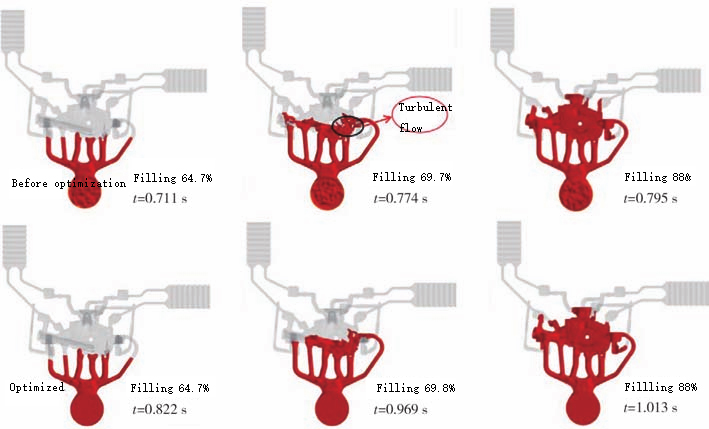
Figure 3 Simulation results of mold filling speed for two schemes It can be seen that temperature distribution in Scheme 1 is very uneven. There is a large area near middle of casting where temperature is lower, not exceeding 630℃, while temperature in other areas reaches above 645℃, forming a large temperature difference. As a result, speed of this area during solidification process is inconsistent, and there is an obvious solidification time difference, resulting in that post-solidified area cannot be fed by molten metal. Serious shrinkage defects are prone to occur. Temperature distribution of Scheme 2 is relatively uniform, and temperature difference at main body of casting does not exceed 3℃. In terms of filling temperature, scheme 2 is better than scheme 1. When filling reaches 40%, filling speed at position A in Scheme 1 is too fast, reaching more than 50m/s, so that faster molten metal will fill casting first, resulting in uneven filling of casting. When filling reaches 73%, because molten metal in area A is filled too fast, an unfilled blank area will be formed when mixed with slower molten metal, as shown in area B in Figure 3c. Because this area is surrounded by two streams of molten metal and then slowly filled, this area is prone to suffocation. When filled to 90%, a large area where it is easy to hold one’s breath appears, as shown in area C in Figure 3e. Compared with Scheme 1, Scheme 2 has a better filling speed simulation effect.
Level
Pouring temperature (A)/℃
Mold preheating temperature (B)/℃
Injection speed (C)/(m*s-1)
1
660
160
4.5
2
680
180
5.5
3
700
200
6.5
Table 2 Taguchi test factors-level table
Pouring temperature/℃
Mold preheating temperature/℃
Injection speed/(m*s-1)
Air entrainment rate y1/%
Shrinkage rate y2/%
660
160
4.5
1.47
0.401
660
180
5.5
1.51
0.357
660
200
6.5
1.43
0.398
680
160
5.5
1.44
0.471
680
180
6.5
1.41
0.411
680
200
4.5
1.54
0.393
700
160
6.5
1.46
0.537
700
180
4.5
1.55
0.479
700
200
5.5
1.44
0.457
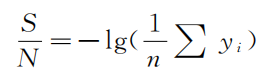
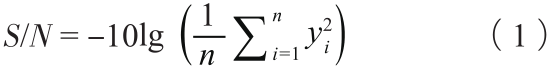
Table 3 Taguchi orthogonal table and result statistics For the two response targets of air entrainment rate and shrinkage porosity, they are both consistent with small characteristics in Taguchi test quality characteristics. Therefore, calculation formula of signal-to-noise ratio S/N is:
In the formula, n represents number of tests; i represents i-th test.
No
y1
S/N1
y2
S/N2
1
1.47
-3.346
0.401
7.937
2
1.51
-3.580
0.357
8.947
3
1.43
-3.107
0.398
8.002
4
1.44
-3.167
0.471
6.540
5
1.41
-2.984
0.411
7.723
6
1.54
-3.750
0.393
8.112
7
1.46
-3.287
0.537
5.401
8
1.55
-3.807
0.479
6.393
9
1.44
-3.167
0.457
6.802
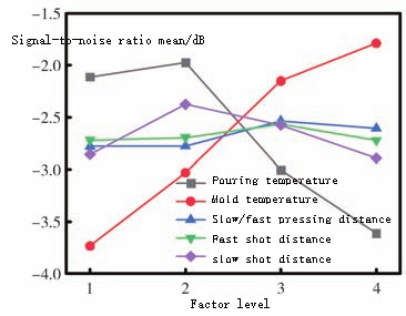
Table 4 Signal-to-noise ratio calculation results When only considering air entrainment rate, it can be seen from Table 5 that C>B>A, that is, influence of die-casting process parameters on air entrainment rate from large to small is: injection speed, mold preheating temperature, pouring temperature. It can be seen that when only considering air entrainment rate, die-casting process parameter combination that satisfies maximum signal-to-noise ratio S/N1 is A2B1C3, that is, pouring temperature is 680℃, mold preheating temperature is 160℃, and injection speed is 6.5m/ s.
Factor
Level
S/N1 mean
Extremely bad R1
S/N2mean
Extremely bad R2
A
1
-3.344
0.119
8.295
2.097
2
-3.301
7.458
3
-3.420
6.198
B
1
-3.267
0.190
6.626
1.062
2
-3.457
7.688
3
-3.341
7.639
C
1
-3.634
0.508
7.481
0.439
2
-3.305
7.429
3
-3.126
7.042
Table 5 Range analysis table
Source
Degrees of freedom
Sum of squared deviations
Mean square
F
Significance
Pouring temperature
2
0.000622
0.000311
0.10
Not obvious
Mold preheating temperature
2
0.001689
0.000844
0.28
Generally
Injection speed
2
0.011622
0.005811
1.93
Significantly
Error
2
0.006022
0.003011
Total
8
0.019956
Table 6 Variance analysis table When only considering shrinkage porosity, it can be seen that A>B>C, that is, influence of die-casting process parameters on shrinkage porosity from large to small is: pouring temperature, mold preheating temperature, injection speed. When only shrinkage porosity is considered, die-casting process parameter combination that satisfies maximum signal-to-noise S/N2 is A1B2C1, that is, pouring temperature is 660℃, mold preheating temperature is 180℃, and injection speed is 4.5m/s.
Source
Degrees of freedom
Sum of squared deviations
Mean square
F
Significance
Pouring temperature
2
0.017095
0.008547
14.96
Significantly
Mold preheating temperature
2
0.005796
0.002898
5.07
Generally
Injection speed
2
0.001022
0.000511
0.89
Not obvious
Error
2
0.001143
0.000571
Total
8
0.025056
Table 7 Variance analysis table
Figure 4 Comparison of air entrainment rate and shrinkage rate before and after optimization
Figure 5 HUD die casting
In conclusion
During die-casting process of AM60B magnesium alloy automobile HUD bracket, when only air entrainment rate is considered, injection speed has the greatest impact, followed by mold preheating temperature, and pouring temperature has the least impact. When only shrinkage porosity is considered, pouring temperature has the greatest impact, followed by mold preheating temperature, and injection speed has the least impact. When air entrainment rate and shrinkage rate are comprehensively considered, optimal process parameter combination is: pouring temperature is 660℃, mold preheating temperature is 200℃, and injection speed is 6.5m/s.
Die castings are widely used in automobiles, medical equipment, electronic equipment, communication equipment and other fields. Their performance will affect service life of entire equipment, it is of positive significance to conduct defect detection and life assessment. Die castings are prone to defects during production process, such as water lines, blistering, shrinkage cavities, discoloration, mechanical strain, deformation, cracks, flash, fleshy and mold-sticking strains, etc. Traditional methods are mostly manual detection, which has poor detection results, is time-consuming and labor-intensive. In recent years, deep learning technology has attracted increasing attention. Its deep integration with factory production can greatly improve detection efficiency of casting defects and improve working environment. Researchers improved YOLACT algorithm, which can identify defects and perform semantic segmentation. There were 67 sub-defects and 2,727 defect maps in test. Defect recognition rate increased from initial 62.0% to 65.8%, and detection rate was also optimized. Cascade model is used to solve problems of missing samples and uneven proportions, and defect coordinates are determined by comparing positive samples with defective samples. At the same time, by training Mask-RCNN model, defects can be directly located and defect types identified. Use lighter MobileNetv2 network to replace original backbone network DarkNet53 of Yolov3, introduce CIoU mechanism to more accurately calculate position loss. For a data set mainly composed of scratch defects, defect recognition rate is increased by 5% based on original Yolov3 model, and detection speed is increased by 23 f/s. Two aluminum die-casting defect sets are generated through three-dimensional ellipsoid model and GAN model. Defect set consists of a large number of normal castings and a small number of defective castings. Results show that three-dimensional ellipsoid model is more effective than GAN model, with mAP (mean average precision) reaching 71.02%. BX-Net network using DenseNet121 as backbone can identify defects in X-ray images of aviation castings with an accuracy of 99%. Current research suffers from lack of data sets and single defect types, which cannot better reflect complexity of actual production, or defect types can reflect actual situation but model accuracy is not enough. This study expanded collected data set through self-developed software to improve model identification capabilities. Defect set used has 21 kinds of defects, which has many types and can better reflect actual production situation. At the same time, model is optimized to improve accuracy and efficiency of defect detection, aiming to provide a reference for defect detection of similar castings.
Graphical results
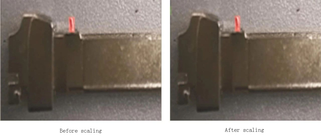
Data set plays role of “trainer” and “detector” in deep learning detection. Lack of data sets will lead to problems such as overfitting and inaccurate detection of model. Since there are fewer defective parts in actual production, data set obtained through actual sampling alone is far from enough. Therefore, when there are few samples, geometric transformations, such as rotation and scaling, are used to expand data set to better assist model defect identification. Augment data set through rotation and scaling. Step of rotation is to set an angle starting point and end point, and give program a certain step length. Image is automatically rotated and transformed through program, as shown in Figure 1, and xml file is generated based on pre-annotation file. Scaling is divided into equal scaling and non-equal scaling, see Figure 2 and Figure 3.
Figure 1 Effect diagram before and after rotation
Figure 2 Effect diagram before and after proportional scaling of length and width
Figure 3 Effect diagram before and after specifying length and width scaling Mosaic data enhancement method evolved from CutMix algorithm. Algorithm principles of two are relatively similar, but Mosaic uses 4 pictures for splicing, which better enhances diversity of data. At the same time, pictures with different semantics are also added to enhance robustness of model, enhance normalization layer effect, and improve target detection mAP. Principle is shown in Figure 4. Mixup is a method of linearly mixing images at a certain ratio to expand data set. Through Mixup method, linear expression between training samples can be enhanced, making decision boundaries between classes smoother, improving stability of model training and generalization ability of model, Mixup has less computing overhead. It can expand data set while also taking into account speed of model training.
Figure 4 Principle of Mosaic data enhancement
Figure 5 Defect pictures before Mixup
Figure 6 Defect pictures after Mixup YOLOX is developed based on YOLOV3 model by adding special structures such as anchorless frames and decoupled heads. According to different networks, there are 6 models in total, which are nano, tiny, s, m, l, and x in order of network size. After comprehensive consideration, YOLOX-S model was selected to detect defects in die castings. Network structure of YOLOX model consists of input end (Input), backbone network (Backbone), feature fusion network (Neck), and prediction network (Prediction) using decoupling head. Basic structure of ShuffleNetv2 is composed of three structures: channel splitting, depth-separable convolution and channel shuffling. ShuffleNetv2-plus used is an improved version of ShuffleNetv2, that is, based on original model, Shuffle-Xception module is added; SE channel attention mechanism is introduced in last stage of model training. At the same time, HS (h-swish) activation function is used in last two stages to replace original ReLU activation function and used in conjunction with SE attention mechanism; finally, maximum pooling layer after initial convolution in original model is removed, and dropout mechanism is turned on.
Figure 7 ShuffleNetv2 structure diagram
Figure 8 Shuffle-Xception structure diagram
Figure 9 SE attention mechanism structure diagram Test uses Ubuntu 18.04.01 version, CPU model is Intel (R) Core (TM) i9-10980XE, GPU model is Geforce RTX 3090, quantity is 2, CUDA version is 11.3, python version is 3.8, and pytorch version is 1.10. Original model network structure Darknet53 is replaced by ShuffleNetv2-plus. Initial learning rate is 1*10-3, Epoch is set to 180, optimizer uses adam, momentum is set to 0.937, weight attenuation is set to 0, and only Mosaic data enhancement is turned on. There are 21 types of defects in data set, and there are only 2 pictures of each defect in initial data set. Independently developed a die-casting defect detection software based on YOLOX model. Through data enhancement module of software, original data set is expanded through geometric transformation operations of rotation and scaling, and image label files are automatically generated. Self-developed software can not only expand defective data set, but also skip labeling data set, thus greatly improving work efficiency. At the same time, software also has model training and defect detection functions, which can better monitor model training progress and defect identification.
Figure 10 Die casting defect detection software interface based on YOLOX model
Formula parameters
Meaning
TP(True Positives)
Number of positive samples identified by model is actually number of positive samples.
FP(False Positives)
Number of positive samples identified by model is actually number of negative samples.
FN(False Negatives)
Number of negative samples identified by model is actually number of positive samples
TN(True Negatives)
Number of negative samples identified by model is actually number of negative samples
P(Precision)
Precision
R(Recall)
Recall rate
AP(Average Precision)
Average accuracy
P(r)
Precision rate is plotted on vertical axis and recall rate is plotted on horizontal axis.
Table 1 Evaluation indicator formula parameters
Figure 11 Comparison of results before and after improvement
Figure 12 4 types of defects that are difficult to identify
Model structure
mAP/%
YOLOX
86.51
YOLOX-Glou
86.82
YOLOX-Focal Loss
84.88
YOLOX-GIOU-Focal Loss
84.88
ShuffleNetv2-plus-YOLOX
84.88
Table 2 Comparison of test results of different model structures
In conclusion
In view of difficulties in collecting die-casting defect detection data sets, as well as high labor intensity and low efficiency of defect detection, we independently developed a die-casting defect detection software based on YOLOX model, which can not only expand data set and generate corresponding labels, but also has functions of monitoring model training and defect detection. By using ShuffleNetv2-plus to replace YOLOX’s Darknet53 network structure, average detection rate of die-casting defects by improved YOLOX model increased from original 86.51% to 89.19%.
Electroplating is a process that uses principle of electrolysis to plate a thin layer of other metals or alloys on the surface of certain metals. It is a process that uses electrolysis to attach a metal film to the surface of metal or other material parts to prevent metal oxidation (such as rust), improves wear resistance, conductivity, reflectivity, corrosion resistance (copper sulfate, etc.) and improves appearance. Outer layer of many coins is also electroplated.
Related effects
A technology that uses principle of electrolytic cells to deposit metal coatings on mechanical products that adhere well but have different properties and base materials. Electroplated layer is more uniform than hot dip layer and is generally thinner, ranging from a few microns to dozens of microns. Through electroplating, decorative protective and various functional surface layers can be obtained on mechanical products, workpieces with wear and processing errors can also be repaired. In addition, it has different functions according to various electroplating needs. Examples are as follows: 1. Copper plating: used as a primer to improve adhesion and corrosion resistance of electroplating layer. (Copper is easily oxidized. After oxidation, patina no longer conducts electricity, so copper-plated products must be protected by copper) 2. Nickel plating: used as base or appearance to improve corrosion resistance and wear resistance (chemical nickel has a higher wear resistance than chromium plating in modern processes). (Note that many electronic products, such as DIN connectors and N connectors, no longer use nickel base, mainly because nickel is magnetic and will affect passive intermodulation in electrical performance) 3. Gold plating: Improve conductive contact resistance and enhance signal transmission. (Gold is the most stable and the most expensive.) 4. Palladium-plated nickel: improves conductive contact resistance, enhances signal transmission, and has higher wear resistance than gold. 5. Tin-lead plating: improves soldering ability and is soon to be replaced by other substitutes (most lead-containing products are now plated with bright tin and matte tin). 6. Silver plating: Improve conductive contact resistance and enhance signal transmission. (Silver has the best performance, is easily oxidized, and also conducts electricity after oxidation)
Electroplating method
Electroplating is divided into rack plating, barrel plating, continuous plating and brush plating, which are mainly related to size and batch size of parts to be plated. Rack plating is suitable for products of general size, such as car bumpers, bicycle handlebars, etc. Barrel plating is suitable for small parts such as fasteners, washers, pins, etc. Continuous plating is suitable for batch production of wire and strip. Brush plating is suitable for local plating or repair. Electroplating solutions include acidic, alkaline, acidic and neutral solutions with added chromium compounds. No matter what plating method is used, plating tank, hangers, etc. that come into contact with products to be plated and plating solution should have a certain degree of versatility.
Plating classification
According to composition of coating, it can be divided into three categories: single metal coating, alloy coating and composite coating. If classified according to use, it can be divided into: ① protective coating; ② protective decorative coating; ③ decorative coating; ④ repair coating; ⑤ functional coating
Single metal plating
Single metal electroplating has a history of more than 170 years, and 33 metals on periodic table of elements can be produced by electrodeposition from aqueous solutions. Commonly used ones include electroplating of zinc, nickel, chromium, copper, tin, iron, cobalt, cadmium, lead, gold, silver and more than 10 kinds. Coating formed by depositing two or more elements simultaneously on cathode is an alloy coating. Alloy coatings have structural structures and properties that single metal coatings do not have, such as amorphous Ni-P alloys, SN alloys that are not shown in phase diagram, alloy coatings with special decorative appearance, particularly high corrosion resistance, excellent weldability, and magnetic properties.
Composite plating
Composite plating is a process in which solid particles are added to plating solution and co-deposited with metal or alloy to form a metal-based surface composite material to meet special application requirements. According to electrochemical properties between coating and base metal, electroplating can be divided into two categories: anodic coating and cathodic coating. When potential of coating metal relative to base metal is negative, coating acts as an anode when forming a corrosion microbattery, so it is called an anodic coating, such as zinc coating on steel parts; when potential of coating metal relative to base metal is positive, coating acts as cathode when forming a corrosion microbattery, so it is called cathodic coating, such as nickel plating and tin plating on steel parts. It can be divided into: ① Protective coatings: coatings such as Zn, Ni, Cd, Sn and Cd-Sn are used as anti-corrosion coatings that are resistant to the atmosphere and various corrosive environments; ② Protection. Decorative coatings: such as Cu-Ni-Cr, Ni-Fe-Cr composite coatings, etc., which are both decorative and protective; ③ Decorative coating: such as Au, Ag and Cu. Sun imitation gold plating, black chrome, black nickel plating, etc.; ④ Reparative coating: such as electroplating Ni, Cr, Fe layer to repair some expensive wear parts or processing out-of-tolerance parts; ⑤ Functional coatings: conductive coatings such as Ag and Au; magnetic coatings such as Ni-Fe, Fe-Co and Ni-Co; high-temperature anti-oxidation coatings such as Cr and Pt-Ru; reflective coatings such as Ag and Cr; anti-reflective coatings such as black chromium and black nickel; wear-resistant coatings such as hard chromium, Ni and SiC; anti-wear coatings such as Ni, VIEE, Ni, C (graphite); weldable coatings such as Pb, Cu, Sn and Ag; Pb, Cu, Sn, Ag; anti-carburization Cu plating, etc.
Working principle
Electroplating requires a low-voltage, high-current power supply that supplies power to electroplating tank and an electrolytic device consisting of a plating solution, parts to be plated (cathode) and anode. Composition of electroplating solution varies depending on coating, but they all contain main salts that provide metal ions and can complex It is a complexing agent that combines metal ions in main salt to form a complex, a buffer used to stabilize pH of solution, an anode activator and special additives (such as brighteners, grain refiners, levelers, wetting agents, stress relievers and fog suppressors, etc.). Electroplating process is a process in which metal ions in plating solution are reduced to metal atoms through electrode reactions under action of an external electric field, and metal deposition is performed on cathode. Therefore, this is a metal electrodeposition process that includes steps such as liquid phase mass transfer, electrochemical reaction, and electrocrystallization. In plating tank containing electroplating solution, cleaned and specially pretreated parts to be plated serve as cathode, and anode is made of plated metal. The two poles are connected to negative and positive poles of DC power supply respectively. Electroplating solution consists of an aqueous solution containing metal plating compounds, conductive salts, buffers, pH adjusters, additives, etc. After energization, metal ions in electroplating solution move to cathode under action of potential difference to form a plating layer. Metal of anode forms metal ions into plating solution to maintain concentration of metal ions being plated. In some cases, such as chromium plating, an insoluble anode made of lead or lead-antimony alloy is used, which only serves to transfer electrons and conduct current. Concentration of chromium ions in electrolyte needs to be maintained by regularly adding chromium compounds to plating solution. During electroplating, quality of anode material, composition of plating solution, temperature, current density, power-on time, stirring intensity, precipitated impurities, power supply waveform, etc. will all affect quality of coating and need to be controlled in a timely manner. First of all, electroplating solution has six elements: main salt, additional salt, complexing agent, buffer, anode activator and additives. Principle of electroplating includes four aspects: electroplating solution, electroplating reaction, electrode and reaction principle, and metal electrodeposition process. Electrochemical reaction in electroplating reaction: Figure below is a schematic diagram of electroplating device. Part to be plated is cathode, which is connected to negative electrode of DC power supply. Metal anode is connected to positive electrode of DC power supply. Both anode and cathode are immersed in plating solution. When a certain potential is applied between cathode and anode, following reaction occurs at cathode: metal ions Mn+ that diffuse from inside plating solution to interface between electrode and plating solution obtain n electrons from cathode and are reduced to metal M. On the other hand, completely opposite reaction to that at cathode occurs at anode, that is, dissolution of metal M occurs at anode interface, releasing n electrons to generate metal ions Mn+.
After the 1990s, China’s die-casting industry has achieved amazing development and has developed into an emerging industry. At present, aluminum alloy die-casting process has become one of the most widely used processes in automotive aluminum alloy forming processes, accounting for 49% of various automotive forming process methods. There are about 3,000 die-casting companies in China. Output of die-casting parts increased from 266,000 tons in 1995 to 870,000 tons in 2005. Annual growth rate remains above 20%, with aluminum alloy die castings accounting for more than 3/4 of all die casting output. Types of die-casting products in China are diversified, including automobiles, motorcycles, communications, home appliances, hardware products, power tools, IT, lighting, escalator steps, toy lights, etc. With improvement of technical level and product development capabilities, types and application fields of die-casting products continue to expand, its die-casting equipment, die-casting molds and die-casting processes have undergone tremendous changes. Since its commercial production in 1914, die-cast aluminum alloy has developed rapidly with development of automobile industry and invention of cold chamber die-casting machine.
Die-cast aluminum alloys are divided into two types according to their properties: medium and low strength (such as China’s Y102) and high strength (such as China’s Y112). At present, die-cast aluminum alloys used in industry mainly include following series: Al-Si, Al-Mg, Al-Si-Cu, Al-Si-Mg, Al-Si-Cu-Mg, Al-Zn, etc. Improvement of mechanical properties of die-cast aluminum alloys is often accompanied by a decrease in the performance of casting process. High-pressure and rapid solidification characteristics of die-casting make this contradiction more prominent in some aspects. Therefore, general die-casting parts are difficult to undergo solution heat treatment, which restricts improvement of mechanical properties of die-cast aluminum alloys. Although oxygenated die-casting, vacuum die-casting, etc. are effective ways to improve mechanical properties of alloys, widespread adoption is still difficult, so development of new die-cast aluminum alloys has been ongoing. Die-casting process of early horizontal cold chamber die-casting machines had only one speed to send molten metal into mold, and injection speed was only 1m-2m/s. Using this process, there were many pores inside casting and structure was loose. It was soon improved to 2-stage injection, which simply decomposed injection process into two stages: slow speed and fast speed, but fast speed was only 3m/s. Later, in order to increase density of die castings, a stage of pressure increase was added after slow and fast speeds, which became the three stages of slow injection, fast injection and pressurization. This is classic three-stage injection. Compared with ordinary die casting method, vacuum die casting method has following characteristics: 01 Porosity is greatly reduced 02 Vacuum die-casting castings have high hardness and fine microstructure 03 Vacuum die castings have higher mechanical properties Recently, vacuum die casting mainly focuses on extracting gas from mold cavity, and there are two main forms: ① Extract air directly from mold; ② Place mold in a vacuum box to evacuate air. When using vacuum die casting, design of exhaust channel position and exhaust channel area of mold is crucial. There is a “critical area” in exhaust duct, which is related to amount of gas extracted from cavity, exhaust time and filling time. During filling process of molten metal, molten metal should be filled in a dispersed spray state. Size of runner also has a great influence on the effect of oxygenated die-casting. Appropriate runner size can not only allow molten metal to fill mold in a turbulent flow, but also prevent temperature of molten metal from dropping too fast. Highly dispersed distribution of oxides will not have an adverse effect on casting, but can increase hardness of casting and refine structure after heat treatment. Oxygen die casting can be used for Al, Mg and Zn alloys that react with oxygen. At present, oxygenated die casting can be used to produce various aluminum alloy castings, such as: hydraulic transmission housings, heat exchangers for heaters, hydraulic transmission valve bodies, computer brackets, etc. For die castings that require heat treatment or assembly welding, high air tightness and use at higher temperatures, oxygenated die casting has technical and economic advantages. Semi-solid die casting is a technology that stirs liquid metal when it solidifies, obtains a slurry with a solid phase component of about 50% or higher at a certain cooling rate, and then uses slurry for die casting. Semi-solid die-casting technology currently has two forming processes: flow forming process and thixoforming process. The former is to feed liquid metal into a specially designed injection molding barrel, where shear is applied by a spiral device to cool it into a semi-solid slurry, which is then die-cast. The latter is to feed solid metal particles or chips into a spiral injection molding machine, turn metal particles into slurry under heating and shearing conditions before die-casting. The key to semi-solid die-casting forming process is effective preparation of semi-solid alloy slurry, precise control of proportion of solid-liquid components, research and development of automated control of semi-solid forming process.
In order to realize automated production of semi-solid forming, American scientists believe that following technologies need to be vigorously developed: 01 Adaptable and flexible bar transportation 02 Precision die casting lubrication and maintenance 03 Controllable casting cooling system 04 Plasma degassing and treatment Electromagnetic pump low-pressure casting is a newly emerging low-pressure casting process. Compared with gas-based low-pressure casting technology, it is completely different in terms of pressurization methods. It uses non-contact electromagnetic force to directly act on liquid metal, which greatly reduces oxidation and aspiration problems caused by impure compressed air and excessive partial pressure of oxygen in compressed air, realizes smooth transportation and filling of liquid aluminum, and prevents secondary pollution caused by turbulence. In addition, electromagnetic pump system is completely controlled by computer numerical control, process execution is very accurate and repeatable, giving aluminum alloy castings obvious advantages in terms of yield, mechanical properties, surface quality and metal utilization. As research on this technology continues to deepen, process is becoming more and more mature. Through development in recent years, design level, technical parameters, performance indicators, mechanical structure and manufacturing quality of China’s die-casting machines have been improved to varying degrees. In particular, cold chamber die-casting machine has been changed from original fully hydraulic closing mechanism to a toggle closing mechanism. At the same time, automatic loading, automatic spraying, automatic picking up, automatic edge cutting, etc. are also added. Electrical appliances have also been changed from ordinary power supply control to computer control. Control level has been greatly improved. Some have reached or are close to international level, are marching towards large-scale, automation and unitization.
During this period, new domestic die-casting machine companies have emerged one after another, among which Hong Kong Lijin Company is a typical representative. They has developed a number of domestic leading die-casting machine models, such as horizontal cold chamber die-casting machine with maximum air pressure injection speeds of 6m/s (1997) and 8m/s (early 2000), magnesium alloy hot chamber die-casting machine (early 2000), uniformly accelerated injection system (2002), maximum air injection speed of 10m/s and multi-stage die-casting system (Jane 2004), real-time control injection system (August 2004) and large die-casting machine with a clamping force of 30000kN (July 2004), etc. Small and medium-sized die-casting machines are still dominated by domestic equipment. Gap between domestic die-casting machines and foreign advanced die-casting equipment is mainly reflected in following aspects: 01 The overall structural design is backward 02 Serious oil leakage 03 Poor reliability is the most prominent flaw of domestic die-casting machines. 04 Incomplete varieties and specifications, poor supporting capabilities China’s mold industry has developed rapidly. From 1996 to 2004, average annual growth rate of mold output was 14%. In 2003, output value of die-casting molds was 3.8 billion yuan. At present, China’s domestic mold market satisfaction rate is only about 80%, of which medium and low-end molds are main ones. Large and complex precision molds cannot meet needs of national economic development in terms of production technology, mold quality and life, and production capacity. Consumption of automobiles, motorcycle industries and automobile accessories and demand for supporting products provide a broad market for production of die-casting parts. Application of die-casting aluminum alloys in automobiles will also continue to expand. In the future research and development of die-casting technology, deepening of aluminum alloy die-casting will still be a main direction for development of die-casting technology. In order to adapt to market demand, following issues should be further solved in the future: Promote application of new high-strength, high-wear-resistant die-casting alloys, research colorable die-casting alloys, and new die-casting alloys for castings with special safety requirements. 02 Develop die-cast aluminum alloys with stable performance and easy-to-control composition 03 Simplify alloy composition and reduce alloy grades to provide a foundation for green production 04 Further improve new die-casting processes (vacuum die-casting, oxygenated die-casting, semi-solid die-casting, squeeze casting, etc.) 05 Improve ability to respond quickly to market and implement concurrent engineering (CE) and rapid prototyping manufacturing (RPM) technology 06 Carry out research and development of CAD/CAM/CAE systems 07 Develop and apply more die-cast aluminum alloy automotive parts Die-casting aluminum alloy is main body of non-ferrous alloy die-casting, and AI-Si series alloys are main body of die-casting aluminum alloy. Development of die-casting industry has a long way to go. It involves research and development of high-performance alloys and development of process pathways. Practice has shown that it is a wise choice to be enterprise-centered and combine relevant universities and research units. Relevant results we have achieved have been confirmed. To achieve revitalization of the overall die-casting industry, it is also very important to improve performance of die-casting machines, correspondingly improve design and manufacturing level of die-casting molds. In particular, many foreign technical software are introduced and applied. What method is used to verify them? It is worth further research.
As a high-productivity, low-cost near-net-shape process, die-casting is widely used in communications, automobiles, 3C and other fields. Some researchers believe that main problem currently restricting further expansion of application of die-casting technology is porosity of castings and resulting strength issues. In traditional die-casting process, liquid melt fills mold cavity in a turbulent state, so that gas in the cavity cannot be discharged in time and is involved in alloy, forming pore defects, reducing effective bearing area of casting and causing stress concentration, thus reducing mechanical properties of casting. Some people also believe that internal pores are a serious hidden danger of sudden failure during product service. Compared with high-temperature liquid melt used in traditional die-casting, semi-solid slurry with a higher solid phase ratio used in semi-solid die-casting has higher apparent viscosity and laminar flow characteristics, flows smoothly during high-speed filling process, and is not easy to entrain air. Solidification shrinkage of slurry is smaller than that of traditional liquid metal. It can reduce or eliminate defects such as pores and shrinkage, and improve mechanical properties of castings. In addition, since temperature of slurry entering pressure chamber is lower than that of traditional liquid metal, thermal shock to die-casting mold cavity is greatly reduced and service life of mold is extended. Therefore, semi-solid die casting takes into account advantages of semi-solid forming and traditional die casting, and has broad application prospects in industrial applications. Semi-solid die-casting is mainly divided into thixotropic die-casting and rheological die-casting. Due to low secondary heating efficiency of thixotropic die-casting, rheological die-casting has become a research hotspot in the field of semi-solid processing, and its industrial application has received special attention. Preparation of high-quality semi-solid slurry is premise and key to development of rheological die-casting technology. In recent years, a variety of semi-solid slurry preparation technologies have been proposed at home and abroad. Different researchers have developed double-helix shear technology, which uses a pair of high-speed rotating screws to stir melt at high shear rates to prepare semi-solid slurry; developed RSF pulping technology, using entropy exchange materials as cooling media to absorb heat from metal melt to prepare semi-solid slurry; SEED slurry process was proposed. Under low superheat pouring conditions, preparation crucible was eccentrically rotated to produce effective shearing in melt, inhibiting growth of primary phase dendrites, thereby preparing a semi-solid slurry; developed GISS technology, which introduces inert gas when melt solidifies, and uses bubble disturbance to prepare semi-solid slurry; vibrating tilted plate process was developed to prepare semi-solid slurry, which is believed to be combined effect of nucleation thermodynamic conditions and vibration shear collision; LSPSF slurrying process was developed. Alloy melt is poured into the entrance of rotating conveyor pipe. Under combined effects of gravity and shearing/cooling of inner wall of rotating conveyor pipe, alloy is transformed from molten state into a semi-solid slurry with a certain solid phase ratio; SCP technology was developed, in which superheated melt is poured into a vertical serpentine channel to cool down, and disturbance caused by its own gravity is used to prepare a semi-solid slurry. These processes enrich semi-solid slurry preparation technology, promote development and application of rheological die-casting processes. In order to prepare high-quality semi-solid slurry more stably, continuously and efficiently, cater to industrial promotion of rheological die-casting and break through patent protection of foreign pulping processes, it is necessary to develop some new simple, efficient, practical and low-cost pulping technologies. In view of this, an air-cooled stirring rod slurry process (Air-Cooled Stirring Rod, ACSR) is proposed to achieve continuous and rapid preparation of large-volume semi-solid slurry, and is closely connected with die-casting machine to form a rheological die-casting process that integrates slurry preparation, transportation and forming. This study mainly introduces industrialization status of ACSR rheological die-casting process. At the same time, Al-8Si alloy and Al-6Si alloy (Sr modification) are used as raw materials, combined with production of shell parts for 4G/5G communication base stations and new energy vehicles, compared with traditional die-casting, impact of ACSR rheological die-casting process on alloy structure and properties is studied. .
Graphic and text results
Test materials are Al-6Si, Al-8Si high thermal conductivity alloy, Al-7Si-4Cu-0.2Cd high-strength and tough aluminum alloy. Chemical composition is shown in Table 1. Using SETARAM TGA-92 high temperature comprehensive thermal analyzer to perform differential thermal analysis on heating process of alloy, it can be obtained that liquidus temperature and solidus temperature of Al-8Si alloy are 623℃ and 565℃ respectively, liquidus and solidus temperature of Al-6Si alloy are 635℃ and 570℃ respectively, liquidus and solidus temperatures of Al-7Si-4Cu-0.2Cd alloy are 607℃ and 518℃ respectively. Figure 1 shows equipment schematic and physical diagram of aluminum alloy uniform solidification control technology. It mainly consists of a high-pressure gas supply device, an air guide pipe, a stirring rod, an aluminum alloy melt, a crucible and a thermocouple. Size of stirring rod is determined based on volume of aluminum alloy melt and size of scooping spoon. At present, aluminum alloy ACSR slurrying device has been connected with various tonnage die-casting machines. Specific supporting die-casting machine clamping forces are 4000, 8500, 12500, 16000, 20000, 30000 and 40000kN. In addition, ACSR pulping device can be combined with a vacuum mechanism to prepare high-quality semi-solid slurry in a vacuum environment.
Alloy
wB
Si
Fe
Cu
Mg
Zn
Sr
Cd
Al
Al-8Si
7.73
0.53
0.03
0.02
margin
Al-6Si
7.16
0.57
0.02
margin
Al-7Si-4Cu-0.2Cd
7.24
0.18
4.18
0.02
0.24
margin
Table 1 Chemical composition of alloy (%)
Figure 1 Schematic diagram and physical picture of equipment for preparing semi-solid slurry using aluminum alloy uniform solidification control technology
Figure 2 Aluminum alloy ACSR rheological die casting process With increase in integration of signal electrical devices in 5G wireless base stations, communication equipment is developing in direction of ultra-thin and ultra-light, high heat dissipation, high mechanical properties and high corrosion resistance. Combining ACSR pulping technology with die-casting technology, a brand-new, fully automatic, efficient and high-performance large-scale thin-walled die-casting production line integrating uniform solidification control processing, transportation, die-casting and picking-up of aluminum alloys has been established to meet application requirements of communication equipment structural parts. At present, this technology has been applied to important high-quality die-cast structural parts such as 4G/5G wireless base station cooling casings, filters, shielding boxes and mounting brackets. Figure 3 shows several typical large thin-walled die castings of Al-8Si and Al-6Si aluminum alloys for high-performance communications produced using this technology.
(a) 5G communication heat sink 1 Al-8Si
(b) 5G communication heat sink 2 Al-6Si
(c) 5G communication heat sink 3 Al-6Si Figure 3 Several typical Al-8Si and Al-6Si aluminum alloy high-quality large thin-walled rheological die castings for 5G communications
(a) New energy vehicle end cover
(b) Car steering gear connecting pipe
Figure 4 Several typical high-quality automotive ACSR rheological die castings
Craftsmanship
Surface flatness/mm
Surface roughness/μm
Porosity/%
Traditional die casting
0.5~0.6
6.3
2.1
ACSR rheological die casting
0.20~0.25
3.2
0.9
Table 2 Comparison of surface quality and porosity of aluminum alloy 5G communication casings produced by traditional die casting and rheological die casting
(a) Al-8Si alloy, traditional die casting (b) Al-8Si alloy, ACSR rheological die casting
(c) Al-6Si alloy, traditional die casting (d)Al-6Si alloy, ACSR rheological die casting
(e) Al-7Si-4Cu-0.2Cd alloy, traditional die casting (f)Al-7Si-4Cu-0.2Cd alloy, ACSR rheological die casting Figure 5 Microstructure of conventional die-casting and ACSR rheological die-casting Al-8Si, Al-6Si and Al-7Si-4Cu-0.2Cd alloy samples It can be seen that there are more dendritic α-Al in structure of traditional die castings, more shrinkage cavities and shrinkage porosity defects can be observed. However, a large number of small, nearly spherical primary α-Al grains can be observed in structure of ACSR rheological die castings, and internal defects are significantly reduced. In addition, secondary α-Al grains and eutectic Si in ACSR rheological die castings have also been refined to a certain extent. According to relevant research, it can be seen that Fe-rich phase in ACSR rheological die-casting aluminum alloy is evenly distributed in eutectic structure, and average size is smaller than that of traditional die-casting alloy.
Alloy
Technology
Tensile strength/MPa
Yield strength/MPa
Elongation/%
Thermal conductivity/(W·m-1·K-1)
Al-8Si
HPDC
2203.6
1081.6
4.01.4
1381.7
Rheo-HPDC
2663.1
1291.3
6.41.2
1521.6
Al-6Si
HPDC
1892.9
1021.5
6.11.5
1731.6
Rheo-HPDC
2263.0
1171.2
10.71.6
1861.4
Al-7Si-4Cu-0.2Cd (vacuum ACSR+T6 heat treatment)
HPDC
3654.7
2082.7
5.01.4
Rheo-HPDC
4473.9
3131.9
6.71.5
Table 3 Mechanical and thermal properties of ACSR rheological die-casting and traditional die-casting Al-8Si, Al-6Si and Al-7Si-4Cu-0.2Cd alloys
In conclusion
(1) Developed a stable and efficient integrated process of semi-solid slurry preparation and die-casting, namely ACSR rheological die-casting process, and established a number of new aluminum alloy uniform solidification controlled slurry, transportation, die-casting and part-picking integrated, fully automatic, efficient and high-performance rheological die-casting production lines, realizing industrialization of rheological die-casting of high-quality large-scale thin-walled aluminum alloy structural parts. (2) Compared with traditional die-casting, aluminum alloy castings produced by ACSR rheological die-casting process have better surface quality and lower porosity. Flatness is only 0.20~0.25mm, surface roughness is reduced to 3.2μm, and porosity is reduced to 0.9%. (3) Compared with traditional die-casting alloys, ACSR rheological die-casting aluminum alloys have better mechanical properties and thermal conductivity. Its tensile strength and elongation are increased by 20%~22% and 34%~75% respectively, thermal conductivity is increased by 7.5%~10.1%.
In order to meet requirements of high air tightness and high strength of automotive aluminum alloy oil pump body die-casting parts, to solve problems of shrinkage and cavity defects in castings, die-casting process was designed and optimized. First, casting process was analyzed, pouring overflow system was designed based on experience and process parameters were initially selected. Then Taguchi orthogonal test method was used to design a 5-factor, 4-level die-casting process parameter scheme, and Procast was used for numerical simulation. 16 sets of orthogonal test results were subjected to range and variance analysis based on signal-to-noise ratio. Results showed that mold temperature has the most significant impact on shrinkage and shrinkage cavities. Optimal process parameters of five factors are: pouring temperature 650 ℃, mold temperature 240 ℃, slow/fast injection distance 200 mm/60 mm, fast injection speed 3.0 m/s, slow injection speed 0.2 m/s. Numerical simulation results show that shrinkage and shrinkage volume of casting under this process parameter combination is 1.067 cm³, which is 26.5% lower than before optimization. Mold test results show that appearance of casting is intact, and X-ray flaw detection in key parts shows no obvious shrinkage cavities; metallographic microscope (OM) and scanning electron microscope (SEM) are used to observe structure of casting, and it is found that structure of each area of casting is dense; mechanical property test shows that, microhardness of die casting is greater than HV85, average tensile strength of test rod under same process is 253.36 MPa, and casting meets usage requirements. Automobile oil pump body is a pressure-bearing sealing part. It works in high temperature, high pressure and engine oil environments, has high requirements for high temperature corrosion resistance and air tightness. Due to sensitivity of new energy vehicles to cruising range, their demand for lightweighting is more significant than that of traditional fuel vehicles. Aluminum alloys have become preferred material for automotive parts such as oil pump bodies for oil trucks and hybrid vehicles due to its high specific strength and corrosion resistance. High-pressure casting has advantages of high production efficiency, high dimensional accuracy of castings, good surface and mechanical properties. Therefore, it is widely used in production of complex parts such as aluminum alloy cylinder blocks, pump bodies, and shells. However, due to improper processes and other reasons, die-cast seals often have pores, shrinkage cavities, and shrinkage defects. Existence of pore defects will reduce strength and air tightness of sealing castings, making them unusable. Reasonable die-casting process parameters are a necessary condition for obtaining qualified castings, but there are many factors that affect quality of castings, and value ranges of each factor are wide. Obtaining reasonable process parameters often requires a large number of tests. Use of numerical simulation combined with orthogonal experiments can effectively determine reasonable process parameters. Li Yang et al. used a combination of orthogonal experiments and numerical simulations to explore effects of mold temperature, fast and slow pressure switching points and fast injection speed on pores of aluminum alloy motorcycle cylinders. Results showed that pore area of casting is negatively correlated with fast injection speed, positively correlated with speed switching point and mold temperature. ApparaoK C et al. explored effects of pouring temperature, injection pressure, pouring time and mold temperature on pores of aluminum alloy castings. They concluded that pouring temperature and mold temperature have a significant impact on pores of castings, and an orthogonal experiment based on signal-to-noise ratio was used to optimize process parameters with the smallest pores. GuptaAK et al. used genetic algorithm and fuzzy logic method to obtain optimal combination of five die-casting process parameters including solidification time, pouring temperature, injection pressure and die-casting machine plunger speed, which reduced probability of die-casting defects such as shrinkage holes and cracks in aluminum alloy carburetor shell castings by 58.28%. In summary, it is common and efficient to use numerical simulation combined with optimization methods such as orthogonal experiments or genetic algorithms to optimize die-casting process, and effect of reducing porosity of die-casting parts is also very significant. However, above studies have not completely selected influencing factors of casting porosity defects, research on influencing factors of individual shrinkage porosity and shrinkage cavity defects also needs to be in-depth. Therefore, in order to explore influence of various factors in die-casting process on shrinkage and cavity defects in oil pump body, this article selects main die-casting process parameters of pouring temperature, mold temperature, slow/fast injection distance, fast injection speed and slow injection speed. Using a combination of orthogonal experiments and numerical simulations based on signal-to-noise ratio, shrinkage and porosity rates of castings are optimized as indicators in order to find the best combination of process parameters for castings under a specific pouring and overflow system design.
1. Die-casting process analysis and pouring overflow system design
1.1 Analysis of die-casting process of oil pump body parts
Oil pump body is a pressure-resistant seal that has high requirements for strength and air tightness. Therefore,defects such as cracks, looseness, and bubbles are not allowed in sealing area of casting. Defects such as strain, undercasting, mold sticking, and cold shutoff are not allowed on the surface. Surface roughness is not greater than Ra=6.3 μm, and dimensional tolerance should meet requirements of GB/T 6414-2017. Outline dimensions of oil pump body are 203.9 mm * 108.5 mm * 154.8 mm. Weight of casting blank is 0.65 kg, volume is about 240 cm³, maximum projected area is 109.6 c㎡, and maximum cross-section is surface I, which is assembly surface of pump body and pump cover. Considering that castings II and III require lateral core pulling, casting can choose I side as main parting surface and use bottom injection pouring. Oil pump body model and wall thickness are shown in Figure 1.
Figure 1 Three-dimensional model of oil pump body and analysis of its wall thickness Oil pump body casting has an irregular structure and uneven wall thickness. Maximum wall thickness in sealing area reaches 13.6 mm, the thinnest wall thickness is only 1.5 mm, and average wall thickness is about 4.5 mm. According to casting structure and die-casting empirical formula, process parameters of casting can be preliminarily determined as follows: pouring temperature 660 ℃, mold temperature 210 ℃, slow/fast injection distance 195 mm/65 mm, fast injection speed 2.75 m/s, slow injection speed is 0.25 m/s. Since ADC12 alloy has advantages of good casting performance, high strength, low density and low shrinkage, this alloy is selected as material for oil pump body casting. Its alloy composition is shown in Table 1.
Si
Cu
Mn
Mg
Fe
Zn
Pb, Ti, Sn, Cd
Ni
Al
10.35
1.95
0.25
0.24
0.72
0.61
Each contains 0.1
0.04
margin
Table 1 Chemical composition of ADC12 alloy wB/%
1.2 Design of pouring and overflow system
Oil pump body is a cylinder-type casting with a complex structure, uneven wall thickness, and is concave in multiple directions. It requires side core pulling, so die-casting mold can only use one mold and one cavity. Based on projected area of casting, structure of casting and its ideal injection pressure range, a 500 t horizontal cold press chamber die-casting machine was selected. The total length of press chamber is 515 mm and punch diameter is 75 mm. In order to ensure smooth flow of molten metal during mold filling process, prevent air entrainment, and facilitate removal of pouring system, a “comb-shaped” side pouring method with 6 trapezoidal lateral runner was designed. The total area of inner runner is 221 mm2, gate is set at upper edge of oil pump body and protruding parts on both sides, as shown in Figure 2.
Figure 2 Design of pouring and draining system for oil pump body casting Pouring and overflow system of oil pump body casting consists of a cake, a sprue, 6 lateral sprues, 6 injectors, 8 overflow slots and 2 exhaust slots. Main parameters of each part are shown in Table 2 Show.
Total volume V/cm3
Casting volume V/cm3
Gating system volume Vg/cm3
Overflow system volume Ve/cm3
Gate cross-sectional area Ag/mm2
Casting surface area Af/cm2
Casting solidification modulus M/cm
613
240
283
90
221
94
2.55
Table 2 Main parameters of pouring and drainage system
2. Orthogonal design of die-casting parameters and optimization of process parameters
2.1 Initial and boundary conditions of numerical simulation of die casting
On the premise of ensuring reliable numerical simulation results and reducing calculation time as much as possible, this study uses Procast software to divide non-uniform grids. Set grid unit size in thinner wall thickness of molten metal filling areas such as castings, gating systems and overflow systems to 1.5 mm, and set grid unit size in other areas to 3 mm, set grid unit size of metal parts such as molds, barrels and punches to 10 mm. The total number of grids is approximately 4.54 million. Casting material is ADC12 aluminum alloy, mold material is H13 hot work die steel, and initial conditions of materials are same as those in literature.
2.2 Die-casting numerical simulation plan and results
Oil pump body castings have high requirements for internal quality and air tightness, defects such as cracks, looseness, and bubbles are not allowed inside castings. There are many factors that affect die-casting quality. Relevant production practices and literature research show that process parameters that have an important impact on forming quality of cylinder die-casting parts are pouring temperature (A), mold operating temperature (B), and slow/fast injection distance (C), fast injection speed (D) and slow injection speed (E). Therefore, these five parameters are selected as influencing factors of shrinkage and cavity defects in orthogonal test of this article. Other parameters are set to a certain value according to actual production situation, and their influence is not considered for the time being. 5-factor 4-level orthogonal test parameters are formulated as shown in Table 3.
Level
Factor
Pouring temperature/℃
Mold temperature/℃
Slow/fast injection distance/mm
fast injection speed/(m*s-1)
slow injection speed/(m*s-1)
1
630
180
180/80
2.0
0.1
2
650
200
190/70
2.5
0.2
3
670
220
200/60
3.0
0.3
4
690
240
210/50
3.5
0.4
Table 3 Factors and levels of orthogonal test This article conducts tests in accordance with L16 (45) standard orthogonal test plan, uses Procast’s Visual-Cast module to conduct numerical simulations of die-casting filling and solidification process, prediction of shrinkage and porosity defects. Using shrinkage porosity and shrinkage porosity as evaluation indicators, use cutoff-info function in Procast Visual-Viewer module to count the total shrinkage porosity index of casting, which is volume of part above 3% (hereinafter referred to as shrinkage porosity volume, V-shrinkage). The larger volume, the greater probability that shrinkage holes will appear in corresponding parts of casting. Results of numerical simulation cross test of 5-factor and 4-level die-casting parameters are shown in Table 4.
2.3 Die-casting parameter simulation orthogonal test optimization results and analysis
2.3.1 Analysis of orthogonal test results based on signal-to-noise ratio
Signal-to-noise ratio is used as basis for judging stability of test. Large-scale characteristics, small-scale characteristics and large-scale characteristics will be selected according to different applications. Purpose of orthogonal test in this study is to reduce shrinkage cavity volume of casting, so small characteristics were chosen. If small characteristic does not take a negative value, the smaller value, the better. Signal-to-noise ratio criterion is shown in Equation (1). In formula: S/N is signal-to-noise ratio; yi is i-th test result, and n is number of tests. Lower part of Table 4 is range table of signal-to-noise ratio corresponding to shrinkage pore volume of oil pump body casting. Ki is average value of signal-to-noise ratio of all shrinkage pore volumes under i-th level of different factors. Figure 3 is a line chart of level of each factor in casting and average signal-to-noise ratio of shrinkage pore volume. It can more intuitively reflect influence of each factor on shrinkage pore volume of casting than range chart line chart.
Figure 3 Influence of levels of various die casting factors on shrinkage and shrinkage cavities The greater signal-to-noise ratio, the smaller volume of predicted shrinkage porosity index. As can be seen from Figure 3, the best process parameter values after optimization of orthogonal test are: pouring temperature 650 ℃, mold temperature 240 ℃, slow/fast injection distance 200/60 mm, fast pressing speed 3.0 m/s, slow pressing speed 0.2 m/s. Table 5 shows variance analysis of each process factor. F critical value is 2.490. When F>F critical value, it means that this factor has a significant impact on shrinkage and cavity defects of castings. Based on analysis of Table 4 and Table 5, it can be concluded that influence of various factors on shrinkage and shrinkage holes of castings is: mold temperature > pouring temperature > slow injection speed > slow/fast injection distance > fast injection speed. That is to say, influence of mold temperature is significant, influence of pouring temperature is relatively significant, influence of slow/fast injection distance and slow injection speed is not significant, and influence of fast injection speed is minimal.
Test number
Test plan
Numerical simulation results
A
B
C
D
E
Shrinkage volume/cm2
Signal to noise ratio/dB
1
630
180
180/80
630
180
1.497
-3.50
2
630
200
190/70
630
200
1.301
-2.29
3
630
220
200/60
630
220
1.153
-1.24
4
630
240
210/50
630
240
1.178
-1.42
5
650
180
190/70
650
180
1.452
-3.24
6
650
200
180/80
650
200
1.315
-2.38
7
650
220
210/50
650
220
1.319
-1.13
8
650
240
200/60
650
240
1.141
-1.15
9
670
180
200/60
670
180
1.526
-3.67
10
670
200
210/50
670
200
1.473
-3.36
11
670
220
180/80
670
220
1.384
-2.82
12
670
240
190/70
670
240
1.282
-2.16
13
690
180
210/50
690
180
1.683
-4.52
14
690
200
200/60
690
200
1.601
-4.09
15
690
220
190/70
690
220
1.483
-3.42
16
690
240
180/80
690
240
1.322
-2.42
Signal-to-noise ratio
Mean K1
-2.112
-3.732
-2.780
-2.720
-2.857
Range analysis
Mean K2
-1.795
-3.030
-2.777
-2.695
-2.377
Influence level
B>A>E>C>D
Mean K3
-3.002
-2.152
-2.537
-2.695
-2.575
Mean K4
-3.612
-1.788
-2.607
-2.537
-2.893
Extremely bad R
1.637
1.944
0.243
0.158
0.516
Optimization
A2
B4
C3
D3
E2
Table 4 L16(45) orthogonal simulation test results
Factor
Sum of squared deviations
Degrees of freedom
F value
F critical value
Significance
A
7.170
3
2.066
2.490
Relatively significant
B
9.220
3
2.657
2.490
Significantly
C
0.180
3
0.052
2.490
Not obvious
D
0.067
3
0.019
2.490
Minimal impact
E
0.716
3
0.206
2.490
Not obvious
Error
17.35
15
Table 5 Variance analysis results
2.3.2 Die casting filling and solidification analysis
Above-mentioned optimal die-casting process parameters and parameters before optimization were selected and simulated in Procast respectively. The total filling time before and after optimization was 0.802 s and 1.002 s respectively. Filling process is shown in Figure 4. It can be seen from Figure 4 that during filling process before optimization, when the first stream of molten metal passes through inner runner (slow pressure distance 195 mm), it begins to enter rapid injection stage. Flow speed of molten metal suddenly increases, it is sprayed from inner runner at a very high speed, hits core and cavity wall, violently scouring mold, which not only causes splashing, but also shortens life of mold. When filling is 69.7%, molten metal passing through two sprues on the right side of casting merges at maximum wall thickness of casting at a very high speed. The two molten metals collide with each other, forming a turbulent flow and involving a large amount of gas, which oxidizes molten metal and reduces feeding ability, increasing tendency of shrinkage and shrinkage cavities. In addition, wall thickness here of casting is the largest, heat dissipation during cooling process is slow and it is easy to form an isolated liquid phase area, which makes exhaust difficult, further increasing possibility of forming pores. Slow injection speed of optimized post-filling process is small. During slow pressing, injection punch moves at a smaller speed. Molten metal flows calmly in pressure chamber and slowly fills mold cavity in a laminar flow manner, without involving a large amount of air. At the same time, a smaller slow pressing speed and a longer slow pressing distance correspond to a longer slow pressing time. Gas in cavity during filling process has more time to be eliminated, which reduces probability of pores in casting. Optimized slow injection stroke is 200 mm. When molten metal fills about 15% of cavity volume (including castings, overflow and exhaust systems) through inner runner at a slow injection speed, it enters rapid injection stage. Front part of molten metal that enters mold cavity is filled slowly, and quickly filled part of metal at the back has front part of molten metal as a buffer to reduce direct impact on mold, thereby extending life of mold. When filling 69.8%, speed of the two molten metals that merge at maximum wall thickness of casting is small and will not violently disturb each other to form severe turbulence, reducing tendency of casting to form pores.
Figure 4 Comparison of casting filling process before and after process optimization
2.3.3 Die-casting solidification process and defect analysis
Time when the overall solidification fraction of two sets of process plans before and after optimization is 96% is 31.4s and 34.6s respectively. Time difference is not big. Solidification process of castings before and after optimization is also similar, as shown in Figure 5. Solidification starts at thin wall of casting, exhaust groove and the two outer sprues, then solidifies at thick wall of casting, overflow tank and three middle sprues, finally solidification of final filling area of casting and material cake. From perspective of the overall solidification sequence, maximum wall thickness of casting is after runner and overflow tank solidify, forming an isolated liquid phase area. This area does not receive external feeding during solidification process, shrinkage pit defects are easily formed. In actual production process, it is necessary to increase cooling rate and prioritize solidification to reduce degree of shrinkage defects or avoid their occurrence.
Figure 5 Casting solidification process Critical feeding solid phase ratio of ACD12 aluminum alloy is 0.7. It is generally believed that after solidification fraction of casting is greater than 70%, molten metal no longer has macroscopic feeding ability. When solidification fraction of casting is 70%, a comparative analysis of final solidified area of casting before and after optimization process is performed, as shown in Figure 6.
Figure 6 Comparison of isolated liquid phase area at maximum wall thickness of casting before and after process optimization Solid phase rate in this area of casting before and after optimization is lower than 100%, and temperature is higher than surrounding temperature of casting, which further proves that an isolated liquid phase region appears here in casting. However, cross-sectional area of isolated liquid phase area after optimization is significantly smaller than before optimization, indicating that optimization of process parameters can significantly improve shrinkage defects of castings. As can be seen from Figure 7, the overall shrinkage and cavity defects of casting are significantly reduced after optimization. Before optimization, single largest shrinkage cavity index volume appears at maximum wall thickness A of casting with a volume of 0.988 cm³, and probability is 48.14%, which is likely to form shrinkage defects. After optimization, index volume at A is 0.762 cm³, probability is 24.65%, and probability of shrinkage defects is reduced. After optimization, volume and probability of shrinkage defects in the overall casting and at maximum wall thickness are reduced compared with before optimization. The overall shrinkage porosity index volume of casting before and after optimization is 1.452 cm³ and 1.067 cm³ respectively. After optimization, shrinkage porosity index volume is reduced by 26.5% compared with before optimization.
Figure 7 Comparison of shrinkage and cavity defects in oil pump body castings before and after process optimization Reason for reduction of shrinkage porosity defects in oil pump body castings is firstly because pouring temperature of optimized molten metal is 10℃ lower, and cooling volume of the molten metal shrinks less, resulting in a smaller volume of shrinkage cavities; secondly, after optimization, the mold temperature is 30℃ higher, temperature difference between mold and molten metal is small, flow and feeding ability of molten metal is stronger, and tendency to form shrinkage holes is smaller; thirdly, after optimization, slow injection distance is long and speed is slow, so that molten metal flows slowly, does not involve too much gas to oxidize and reduce feeding ability; fourth, after optimization, injection speed is fast, injection specific pressure is large, volume of casting shrinks during solidification process. When runner still has ability to feed, higher pressure will push more molten metal in gating system to feed, reducing shrinkage and cavity defects in castings.
3. Casting quality analysis
Using die-casting mold in Figure 8a and optimized process parameters for trial production, formed oil pump body casting is shown in Figure 8b. It can be seen from Figure 8b that front and back surfaces of casting are smooth and clean, without defects such as cracks, strains, bulges, and undercasting. Surface quality meets process requirements.
Figure 8 Die casting production In order to check internal quality of casting, X-ray flaw detection was performed on it, and results are shown in Figure 9. Comparing flaw detection results in Figure 9 with numerical simulation prediction results in Figure 7, it can be seen that location of shrinkage holes in oil pump body casting is basically consistent with prediction results, which shows that prediction results of simulation test are relatively accurate. Locations of tiny shrinkage cavities in casting are A and B in Figure 9. These two locations are outer areas of casting and have little impact on sealing performance of oil pump body. In production, taking appropriate spot cooling measures to increase cooling rate here can reduce probability of holes.
Figure 9 X-ray flaw detection results In order to further analyze internal structure and quality of oil pump body casting, thin-walled part and maximum wall thickness A of casting in Figure 9 were cut and sampled for observation with a metallographic microscope (OM). It can be seen from Figure 10a that solidification process at position C of thin wall of casting has fast heat dissipation, large undercooling, high nucleation rate, and short solidification time. Relatively small spherical primary α-Al phase and fine strip-like Al-Si eutectic phase are obtained. Grain size is relatively fine and distribution is relatively uniform. Thin wall C of oil pump body solidifies preferentially under high pressure, so structure is dense and has no shrinkage defects. Scanning electron microscopy (SEM) and OM observation were performed on thick wall A of casting, as shown in Figure 10b. Grains at thick wall A of oil pump body are relatively coarse and uneven in size. Metallographic structure is mainly a coarse massive primary α-Al phase and a needle-like Al-Si eutectic phase. Fine Si particles are embedded in primary α-Al phase for strengthening, and fine shrinkage defects are distributed at the junction of two phases. Grain size is larger at thick wall of casting, and there are shrinkage defects, as shown in Figure 10b. Coarse needle-shaped Al-Si eutectic has a stronger splitting effect on matrix than strip-shaped one, so structural mechanical properties of thick-walled part of casting must be worse than those of thin-walled part. A sample was taken from thick wall A for tensile testing, and its cross section was observed by SEM. As shown in Figure 10c, tensile section is uneven, with a large number of cleavage planes and tearing edges. Cleavage surface is large and there are a few dimples. It is a fracture mode that mixes brittle fracture and ductile fracture. It is a quasi-cleavage fracture, which is consistent with low toughness of ADC12 material. In order to verify whether mechanical properties of casting meet usage requirements, 5 points are taken for hardness testing at thick wall A of casting. As shown in Figure 10d, minimum microhardness in sampling point is HV85.4, average microhardness at thick wall A is HV93.4, and hardness of ADC12 aluminum alloy oil pump body is required to be no less than HV85. At the same time, 5 B-type tensile specimens were die-cast with same molten aluminum furnace and same process parameters for tensile testing. Average tensile strength of sample is 236.6 MPa, which meets domestic requirement of tensile strength ≥ 230 MPa for corresponding brand YZAlSi11Cu3 alloy. Therefore, oil pump body casting meets mechanical property requirements of product.
Figure 10 OM, SEM structure, tensile fracture morphology, tensile strength and microhardness of oil pump body casting
4 Conclusion
(1) Taguchi orthogonal simulation test results show that influence of various die-casting process factors on shrinkage and shrinkage holes in oil pump body castings is: mold temperature > pouring temperature > slow injection speed > slow/fast injection distance > fast injection Speed, among which mold temperature has a significant impact, pouring temperature has a significant impact, slow/fast injection distance and slow injection speed have no significant impact, and fast injection speed has the least impact. (2) Optimized process parameters are: pouring temperature 650 ℃, mold temperature 200 ℃, slow/fast injection distance 200/60 mm, fast injection speed 3.0 m/s, slow injection speed 0.2 m/s . Numerical simulation results show that using this set of process parameters, molten metal filling during die-casting process is stable, and shrinkage porosity volume index is the smallest, which is 26.5% lower than before optimization. Predicted location of shrinkage cavities is basically consistent with the X-ray flaw detection results. (3) Castings tested using optimized process parameters have a good appearance, sealing area has a dense structure, there are no obvious shrinkage holes and cracks. Maximum wall thickness of casting is a quasi-cleavage fracture, which is consistent with low toughness of ADC12 material. Average tensile strength of tensile specimens under same aluminum melt furnace and same process parameters is 236.6 MPa, average microhardness of thick wall of casting is HV93.4, and oil pump body casting meets usage requirements.
Pressure casting (die casting for short) has characteristics of high production efficiency, short production process, high casting finish and strength, small machining allowance, and saving of metal materials. China’s die-casting industry has developed rapidly in recent years, with total output increasing significantly, and it has become a veritable die-casting power. Molds, die-casting machines and die-casting materials are the three major elements of die-casting production. Only high-quality molds can produce high-quality castings stably and efficiently. Working environment of die-casting molds is very harsh: During die-casting production process, mold cavity is in direct contact with high-temperature, high-pressure, and high-speed molten metal, and is directly washed by molten metal. It is prone to wear, high-temperature oxidation, and various corrosions: high-efficiency production causes mold temperature to rise and fall dramatically periodically, and working surface is prone to thermal fatigue cracks: when metal is forced to deform, it rubs against surface of cavity, easily wearing out mold and reducing its hardness. Mold cost is high, production cycle is long, and repair is difficult. Service life is also particularly important. Therefore, research on factors that affect mold performance and service life is beneficial to improving casting quality and reducing economic losses caused by early scrapping of molds. Generally speaking, factors that affect performance and service life of die-casting molds include mold materials, mold design and manufacturing, surface treatment technology and specific usage of mold.
Die-casting molds are very expensive special precision machinery, which require mold maintenance workers not only to have superb skills and meticulous work style, but also to be serious and responsible. Mold maintenance workers should be familiar with technical standards of die-casting molds as follows: 1. It is all about cleaning metal cracks and scales everywhere in mold to reveal true color of mold. 2. Refer to the last die-cast product sent for repair together with mold to carefully check problems with mold. Is there any strain, sticking to mold, pressure or loss of flesh? Is there any small core that is bent or broken? Is there any movable core that is inserted incorrectly in position? Is there a broken push rod or a change in length of push rod? Is there any insert that is not positioned correctly? Is there fastening bolts are loose, etc. Depending on damage, repair or replacement is determined. 3. For cavity collapse, cracks, falling pieces, etc. that cause slight strain on casting, partial welding repairs can be performed. Welding repairs should be performed strictly according to welding repair process, otherwise a lot of mold life will be lost. Above failures of smaller molded parts are more serious or mold is damaged. 4. If molding surface of larger molded parts is seriously collapsed, cracked, or dropped, it can be repaired locally by welding. Welding repair should be performed strictly according to welding repair process, otherwise a lot of mold life will be lost. Above failures of smaller molded parts are more serious or mold is damaged. 5. Sliding parts such as core pulling mechanisms, guide devices, etc. should be thoroughly cleaned, carefully inspected, and repaired. Re-lubricate with high-temperature grease before assembly. 6. If there is hydraulic core pulling, hydraulic part and mold should be repaired at the same time. When repairing hydraulic part, pay special attention to cleanliness to prevent contamination, otherwise the entire hydraulic system of die-casting machine will be polluted. 7. When mold fails or is damaged during production process, repair plan should be determined according to specific situation. Perform comprehensive repairs as above if necessary. 8. After maintenance of mold has been completed, rust-proof molding surface, parting surface, and installation surface, close and set mold, and place it on backing plate according to installation direction of mold on machine. Mold accessories are placed with mold.
01 Mold material
Performance and service life of die-casting mold are closely related to material of mold. Good die-casting mold manufacturing materials generally have following characteristics: good machinability and forgeability; high wear resistance and corrosion resistance: high strength at high temperatures, high red hardness, high temperature oxidation resistance, impact toughness and tempering stability at high temperatures: good thermal conductivity and fatigue resistance; small thermal expansion coefficient: small heat treatment deformation rate and good hardenability. In the past, 3Cr2W8V hot work die steel was commonly used in China, and life of die-casting mold was about 50,000 mold times. H13 hot work die steel was introduced in the 1990s, and die-casting molds produced have a service life of 150,000 to 200,000 molds. It is currently a widely used die-casting mold material. 3Cr2W8V hot work die steel has high strength and hardness, good cold and heat fatigue resistance, and good hardenability, but has poor toughness and plasticity, short service life, high alloying degree, and high cost. H13 has good comprehensive properties at medium temperature (~600℃), high hardenability (can be hardened in air), low heat treatment deformation rate, and its performance and service life are higher than 3Cr2W8V. Material selection of die-casting mold should not only be based on temperature of casting metal and type of casting metal, but also impact and wear of various parts of die-casting mold by casting metal. The higher temperature, the higher thermal fatigue performance and high temperature performance material should have. Parts that are more severely worn should have higher hardness. Working conditions of die-casting molds are becoming increasingly demanding, and requirements for metallurgical quality, performance, and lifespan of mold materials are constantly increasing. In particular, requirements for material purity and isotropy are higher. Some high-alloy, high-quality, and optimized mold materials are constantly emerging. In turn, it also promotes development of die-casting industry.
02 Mold design and manufacturing
Reasonable mold design is an important prerequisite for extending service life of die-casting molds. Reasonable wall thickness and cooling water channel design can ensure strength and thermal balance of mold. When designing mold, special attention should be paid to the areas where stress concentration and greater abrasion occur during work. Accuracy of each selected part must be reasonable: if gap is too large, heat conduction will be poor, leading to thermal fatigue damage; if gap is too small, extrusion force and tensile stress will occur. Internal stress is easily generated during mold manufacturing process, and internal stress has a great impact on service life of mold. Therefore, in process of manufacturing and processing molds, internal stress should be avoided and eliminated in time. For example, after rough machining, timely stress relief and tempering can be performed, and electric pulses can be used instead of electric sparks to reduce surface tension of mold.
03 Mold surface treatment technology
Through rigorous and reasonable technical treatment of surface of die-casting mold, its performance and life can be greatly improved. Die-casting mold surface treatment technology can be roughly divided into three categories: traditional heat treatment process improvement technology; surface modification technology, such as surface laser treatment technology: coating technology. (1) Improvement technology of traditional heat treatment process. Traditional die-casting mold heat treatment process is quenching-tempering. So-called improvement technology of traditional heat treatment process is to combine quenching-tempering with advanced surface treatment technology. Such as NQN (i.e. carbonitriding-quenching-carbonitriding composite strengthening), surface hardness of mold is higher, internal strength is increased, hardness gradient of casing layer is reasonable, tempering stability and corrosion resistance are improved, the overall performance and service life are greatly improved. (2) Surface modification technology. Surface modification technology refers to use of physical or chemical methods to change properties of mold surface. Generally speaking, there are two types: surface heat, expansion and penetration technology and surface laser treatment technology. Surface heat, expansion and carburizing technologies include carburizing, nitriding, boronizing, carbonitriding, sulfur carbonitriding, etc. Carburizing helps strengthen surface hardness of mold. Carburizing process methods include solid powder carburizing, gas carburizing, vacuum carburizing, and ion carburizing. Vacuum carburizing and ion carburizing have fast carburizing speed, uniform carburizing layer, gentle carbon concentration gradient and small deformation of workpiece. Nitriding process is simple, and nitrided layer of mold has high hardness, good wear resistance, and good mold sticking resistance. Boriding improves surface properties most obviously, and mold hardness, wear resistance, corrosion resistance and adhesion resistance are significantly improved, but process conditions are harsh. Laser treatment of mold surfaces is a technology that has emerged in the past thirty years. It improves surface performance of molds in two ways. One is to melt mold surface with laser and then combine it with carburizing, nitriding, plating and other processes. Another method is to combine laser treatment surface technology with some metal auxiliary materials with better physical properties to integrate them into surface of die-casting mold. (3) Coating technology. Coating technology is to put a layer of protective clothing on mold by coating the surface, such as polytetrafluoroethylene composite plating. Main purpose is to enhance wear resistance, corrosion resistance and cold and heat resistance of mold.
04 Mold use
Choosing a reasonable die-casting process and maintenance are crucial to service life of mold. Most mold damage is caused by improper use and lack of scientific maintenance. First of all, special attention should be paid to temperature control of mold. Mold should be preheated before production and an appropriate temperature range should be maintained during production to prevent surface cracks or even cracking caused by excessive temperature gradients between inner and outer layers of cavity. Secondly, choose a high-quality die-casting release agent with a moderate thickness and evenly coat mold surface, which plays an important role in protecting mold material. Finally, in order to reduce accumulation of thermal stress and avoid cracking of die-casting mold, it is necessary to regularly use techniques such as tempering to eliminate thermal stress.
05 Mold material conclusion
Die-casting mold materials, mold design and manufacturing, mold surface treatment technology and mold usage comprehensively affect performance and service life of mold. Combining these factors and taking effective measures can effectively improve performance of die-casting molds and extend service life of die-casting molds.